Facebook
 Google
 GitHub
 Linkedin
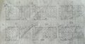
After doing what you tell me, got this.Either you misunderstood your teacher, or the teacher is wrong. With 5 variables, a fully populated truth table would have 32 rows:
View attachment 148684
It's the don't cares in the rows for invalid counts that lets you simplify the logic.
Other than reversing the polarity of the count direction variable, our tables would be the same.
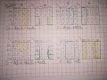
j3= A'Q2Q1Q0 + AQ2'Q1'Q0'
K3= A'Q0 + AQ0'
J2= A'Q0 + AQ0'
K2= A'Q0 + AQ0'
J1= A'Q0 + AQ0'
K1= A'Q0 + AQ0'
Attachments
-
 166.9 KB Views: 13
 -
188.7 KB Views: 4