 Facebook
 Google
 GitHub
 Linkedin
Hi everyone, this is my first thread so be gentle!
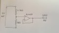
I am trying to monitor a 12V battery voltage using an MSP432 microcontroller ADC. The internal reference of the ADC is 3.3V so I am using a simple voltage divider to bring the 12V down to a suitable range. I am also using a unity gain buffer amplifier to provide some isolation between the battery and the microcontroller.
I'm looking for some general advice around bypass capacitors and where these should be placed. I would expect to add one on the power supply rail to the op amp and perhaps one to bypass the input voltage to ground? Should I also include one between the op amp output and the input to the ADC? If anyone has any rules of thumb for placing and sizing these it would be much appreciated.
The 12V battery drives an AC inverter so I would be interested in any advice to help reduce the "switching noise" present in the voltage measurement.
Attachments
-
 60.3 KB Views: 23
![20170517_091627[1].jpg](/data/attachments/114/114746-a7a3b82ffa9ac07c6db897683fffbe03.jpg)


