Battery powered LED project

John P

Joined Oct 14, 2008
2,068
...You need a few basic functions.

First, use PWM control over your LED brightness. It's more efficient than other methods (e.g. linear control over current) that waste as heat the energy not used by the LEDs. ...
PWM control needs an inductor to store energy, or it won't do anything for you. Just running your LEDs with 20mA half the time as opposed to 10mA all the time isn't going to increase battery life. What really saves energy is using an inductor and not a resistor (or transistor, or voltage regulator) to limit the current.
 

John P

Joined Oct 14, 2008
2,068
I'm afraid I'll stand by what I said. Look at any switching controller for LEDs--they always have an inductor, and they do it because that's the efficient way to use power. Whether you run your lights with high current in PWM mode or low constant current, without an inductor you always have to throw power away in a resistor or transistor.
 

wayneh

Joined Sep 9, 2010
18,147
I thought you might!

My hypothetical PWM scheme using a 555 flasher with NO inductor will flash the LED at 20mA for 10ms every 0.5 seconds (2% duty cycle). It would consume about 1.2mW in the LED plus whatever the 555 uses (very little) plus whatever is lost in regulating the LED current to 20mA.

To deliver the same time-averaged current, your constant-current solution would work out to 0.4mA continuously, which is also 1.2mW average in the LED. Let's assume a current-control IC draws the same power as the 555. But your scheme requires a linear solution - a resistor - to drop from 20mA to 0.4mA. This would divert much more power to heat dissipation than would my PWM circuit.

Ergo, PWM can save a lot of power without any inductor. The savings increase as the duty cycle decreases.

I don't dispute that a proper DC-DC converter will require an inductor, only the statement that PWM won't do anything on its own.

For the OP, could a DC-DC converter be used to provide the two states, "quiet" and "awake", whatever those are?
 
Last edited:
Decimal point slipped, try 14.4 Ah; still a big battery.
Actually seems my first calculation was fine. 0.4A * 360 hrs = 144Ah

Since the OP has dropped the number of LEDs to 20 it's now 72Ah just for the LEDs. Flashing will reduce that. Batteries hate to be run flat, so that's a problem too.

So nope. Not going to happen. Besides your attendants aren't likely going to want to lug around heavy and costly battery packs.

OP any reason solar isn't an option, how did you determine the number of LEDs required?
 
Last edited:

John P

Joined Oct 14, 2008
2,068
I hope I don't really need to explain why a PWM circuit without inductance is no more efficient than a linear circuit. But if I must:

Let's say you want to run an LED with 2-volt forward voltage off a 5V supply, which obviously means the voltage drop in the resistor (or a transistor that's controlled to do the same thing) will be 3.0. Circuit A is linear, and if the desired current is 0.4mA, that says power loss in the resistor will be 0.0004 * 3, or 1.2mW.

Circuit B is a switcher, running at a 2% duty cycle. Current is 50 times higher than in A, so the loss in the resistor is 3 * .020, or 60mW. But the current only flows 2% of the time, so we can calculate a steady-state loss of .060 * .02, or 1.2mW. That's exactly the same as A, but of course it takes a little power to run the oscillator, so it's actually a slightly worse deal.

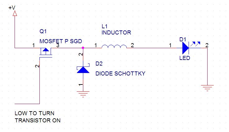
However, if our pointy-haired boss told us to design a driver for an LED to conserve battery power, and we come back with either of those plans, he ought to fire us. We should have used a switching drive with an inductor, like this:


Instead of throwing away energy in a resistor, this driver stores it in the inductor, then uses that stored energy to keep the LED running. It would use that energy to run the LED, so the duty cycle could be less for the same perceived brightness. It's an elementary concept, and it's used everywhere. I'm still a little bemused that I need to explain it--are we really talking about the same thing?

But it's still a so-so design as far as efficiency is concerned. You can get integrated LED drivers where they've done everything to cut losses--see the Maxim catalog, for instance.
 
Last edited:

John P

Joined Oct 14, 2008
2,068
Metalmann, what you might learn is that it's possible to have two people knowing the same things who can nevertheless communicate as if they came from two different planets.

Wayneh, I don't believe you've proved anything--you've offered no diagrams, no equations, and some very mysterious text, like "a linear solution - a resistor - to drop from 20mA to 0.4mA"--that isn't the way Herr Ohm described his celebrated law!

And "whatever is lost in regulating the LED current to 20mA" is power loss in a resistor, is it not? Or in some silicon gadget that limits current while getting warm?

The math here is very simple. If you want to convince me, list a few figures for voltage (i.e. across each component) and current through the various things, instantaneously and averaged. An LED that drops 2V, with the system running off a 5V supply, is a reasonable assumption. So what else is in the circuit?

I think that 3 volts across a 15000 ohm resistor creates a .2mA current, and the power loss in the resistor is .6mW.

3 volts across 300 ohms creates a 10mA current, and power loss is 30mW. Chop that at a 2% duty cycle, and the average current is .2mA, and loss in the resistor is 30mW/50, or .6mW. Can you make the numbers come out any different?

Actually here's another way to think about it: if a pulsed current is more efficient, does the efficiency go up as the duty cycle goes down? What's the limit, in that case?
 

wayneh

Joined Sep 9, 2010
18,147
Well we've totally hijacked the OP's thread. Sorry about that.

And I don't think we're arguing about anything with substance, just two ways to look at saving power while lighting an LED.

But I'll try again to make the point I made above. First the lossy linear situation.

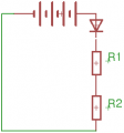
Let's say the battery=6 volts, the LED's Vf=3V, R1=150Ω and R2=7,350Ω

Using both R1 and R2 (7500Ω) limits current to 0.4mA while using only R1 uses 20mA. In this purely linear solution the power wasted in R2 is: 0.0004^2•7,350=1.2mW. That's roughly the same as the power going to the LED.

Now replace R2 with the on/off output of a 555 timer at a 98% duty cycle - so that it lights the LED 2% of the time. The time-average power to the LED and the power lost in R1 are identical to the linear solution. But the 1.2mW loss due to R2 is eliminated.
 

Attachments

John P

Joined Oct 14, 2008
2,068
This has become embarrassing. A point comes where arguing about basic issues is just painful to do, and there's no pleasure in being right. I'm going to back off at this point.

But Wayneh, how about giving some thought to the last line in my previous post. If you're going to claim that a PWM drive is more efficient than pure d.c., wouldn't the duty cycle of the waveform have an effect on that efficiency? Surely it must, because a duty cycle of 99% would be almost the same as a purely linear system, and if you reject that, I could offer you 99.9% or whatever would convince you. You say your 2% duty cycle is better. So if 2% is better than 99%, how about 1%, or 0.1%? Or maybe there's some "sweet spot" where the efficiency is absolutely optimal. A spreadsheet which would generate a plot of efficiency versus duty cycle would be very interesting to see.

As for hijacking the original thread, I say not so! The basic inductive circuit that I drew earlier (07-16-2013, 11:11 AM) is an efficient way to drive LEDs, without any tedious arguments about what kind of resistor to use, because there aren't any resistors. I admit that an integrated LED driver could probably do somewhat better, but it's a starting point. If this project can be built, it has to be done with maximum efficiency in the lighting.
 

wayneh

Joined Sep 9, 2010
18,147
..if a pulsed current is more efficient, does the efficiency go up as the duty cycle goes down? What's the limit, in that case?
R2 in the linear circuit above controls the time-average current to the LED. The limit as R2 approaches zero is 20mA in R1 and the LED.

R2 represents any "linear" solution to dimming the LED off of that 20mA maximum, without using PWM. There is no loss due to dimming when there is no dimming. As detailed above, the dimming loss in R2 can be eliminated using pulsing instead of resistance to reduce the time-averaged current thru the LED.

If the supply to the LED is reasonably efficient at full brightness to begin with, introducing dimming by lowering the PWM duty cycle does not cause much additional loss, whereas a linear solution would.

...there's no pleasure in being right.
It's a rare treat for some of us. ;)
 

Thread Starter

TexAvery

Joined Oct 7, 2009
58
I now know my original plan is not possible. So here is the revised plan.
4 LEDs
I have room for PIR http://www.glolab.com/DP-002A/dp-002A.html
PIR triggers a "waking" fade up to full brightness.
Sleep mode (no movement) LEDs can be dim, maybe half brite.
LEDs only work at night.
Has to function for 30 days on 8 AA batteries, maybe 12 if circuit board is small.
No solar cell charging.
 

wayneh

Joined Sep 9, 2010
18,147
If you can live with 4 LEDs, this opens the possibility of putting them all in series and powering them from 10 or so AAs.

Your PIR sensor needs 3-5V, though, so another approach would be to put your batteries in series-parallel to make 4.5V, and then power your LEDs with a high-efficiency DC-DC converter. I think this is the approach I'd look into.

When motion is detected by the sensor, it produces a voltage. You can use this to turn on a transistor as a switch. You'll need a CdS cell to detect light.

Maybe someone can show us a clever way to "AND" these two sensors together to give the 3 states, LEDs off in the light, dim in the dark with no motion, and bright in the dark when motion is detected.

You mentioned a fade - do you really need that, or is a quick switch OK?
 

John P

Joined Oct 14, 2008
2,068
I think this needs to be a microcontroller based project, where the processor can keep time, respond to the PIR sensor, and generate any PWM frequencies that are required, including producing the fade.

My instinct is that it's better to keep it to 4 batteries, as then you can run the processor directly off their voltage without a regulator, which will cost something in power even if it's not delivering much output. If there's more room, put in bigger batteries (C or D cells). Or you could have pairs or trios of AAs in parallel, I suppose.

For the sake of efficiency, definitely drive the LEDs with a PWM, inductor-based circuit. Maybe build that yourself, or use a commercial chip:
http://www.maximintegrated.com/solutions/white_led_drivers/parts.mvp/scpk/1136/pl_pk/0
 

Bernard

Joined Aug 7, 2008
5,784
I ran a preleminary test using 4 AA NiMH cells driving a faulty boost ckt. lighting 4 yellow LEDs & 100Ω in series.
Off , PS=3 mA, LEDs 0;Dim , PS 13mA, LEDs 5 mA; Bright PS 50 mA, LEDs 20 mA. Pulsing effective with 555 reset. I think 4 C NiMH would be my choice & use 20 % duty cycle both dim & bright; maybe fade slowly,3 sec?, up & down from dim to bright under PIR control.
 
Top