 Facebook
 Google
 GitHub
 Linkedin
Hi all,
I have a number of 12V lead acid batteries which need to be charged and discharged repeatedly. They are discharged in pairs (in series) and in order to discharge them, I have a resistive load of 2.2 Ohms to draw a bit over 10A on average.
This all works fine but I have to continually monitor them to ensure that the total voltage does not drop below 22V to avoid damage to the cells. Therefore, I thought that it must be possible to devise a basic controller for this, with a relay to disconnect the load when done.
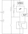
My original thought was to use some zener diodes to control the relay, but it would also be beneficial to log the voltage over time to see what effect the charge/discharge cycles are having. So I thought that maybe a basic microcontroller would be the best bet to do it all - my question is would the basic schematic attached be sufficient, or would I need more interfacing circuitry that would make this more complicated that it's worth?
Note - the potential divider in parallel with the load is purely to scale the voltage for the microcontroller ADC. It is this voltage which would be logged. The button in parallel with the relay is to turn it on initially - provide power to the microcontroller so that it can turn on the relay for sustained operation. Once the end voltage is reached, it can simply turns off the relay and it all shuts off to prevent further drain.
Thanks!
I have a number of 12V lead acid batteries which need to be charged and discharged repeatedly. They are discharged in pairs (in series) and in order to discharge them, I have a resistive load of 2.2 Ohms to draw a bit over 10A on average.
This all works fine but I have to continually monitor them to ensure that the total voltage does not drop below 22V to avoid damage to the cells. Therefore, I thought that it must be possible to devise a basic controller for this, with a relay to disconnect the load when done.
My original thought was to use some zener diodes to control the relay, but it would also be beneficial to log the voltage over time to see what effect the charge/discharge cycles are having. So I thought that maybe a basic microcontroller would be the best bet to do it all - my question is would the basic schematic attached be sufficient, or would I need more interfacing circuitry that would make this more complicated that it's worth?
Note - the potential divider in parallel with the load is purely to scale the voltage for the microcontroller ADC. It is this voltage which would be logged. The button in parallel with the relay is to turn it on initially - provide power to the microcontroller so that it can turn on the relay for sustained operation. Once the end voltage is reached, it can simply turns off the relay and it all shuts off to prevent further drain.
Thanks!
Attachments
-
 80 KB Views: 51
") The output state of the controller cannot be defined when it is not powered, and it could be bad for it to have inputs connected with no connection to both power rails.
The output state of the controller cannot be defined when it is not powered, and it could be bad for it to have inputs connected with no connection to both power rails.


