Facebook
 Google
 GitHub
 Linkedin

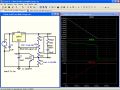
Ok, this one should be so obvious, but I'm not seeing the implementation! I want to make a basic solar battery charger to charge 4 AA batteries, using an LM317T. The output gets a series resistor to limit current, then on to the batteries (in series). My solar panel is capable of delivering 9.5V on a sunny day, so all is good there. This is from a known working schematic from the net.
Now, if I want to add a resistor and LED to the output which will come ON when the 4 batteries reach near full charge, how would I go about that?? My assumption is that current flow will slow as the charge cycle nears its end, and the voltage will rise. I could probably just use a pot to dial in a 'charged vs. uncharged' state for the LED, but I wonder if there is an actual way this is done - maybe by just using the total 6V fully-charged state as the assumption of "LED ON"? Or a voltage divider to make the 6V = the LED turn on voltage?
Thanks for any ideas here, I don't have much time to experiment with this idea!
Now, if I want to add a resistor and LED to the output which will come ON when the 4 batteries reach near full charge, how would I go about that?? My assumption is that current flow will slow as the charge cycle nears its end, and the voltage will rise. I could probably just use a pot to dial in a 'charged vs. uncharged' state for the LED, but I wonder if there is an actual way this is done - maybe by just using the total 6V fully-charged state as the assumption of "LED ON"? Or a voltage divider to make the 6V = the LED turn on voltage?
Thanks for any ideas here, I don't have much time to experiment with this idea!