 Facebook
 Google
 GitHub
 Linkedin
Hi
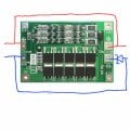
I want use my batteries while them are in charge (I made a mini-UPS for WIFI modem). But my BMS is 3S60A and has 2 ports, one for charge and another for discharge is my wiring correct?! I placed a high amp schottky diode to prevent connect discharge port to charge port. Is that fine or needs two diodes for both + - lines? I think positive lines connected together on PCB!
Thanks
Attachments
Last edited:


