 Facebook
 Google
 GitHub
 Linkedin
Having designed numerous MPPT battery chargers, have never had any reason to implement a boost stage prior to the buck circuit; its just inefficient and a waste of power. Unless you are using tiny PV 6v panels (toys) or something very small, I wouldn't recommend it.
For a battery charger the most important measure is charge current and battery voltage; for mppt the requirement is to measure the instantaneous charge current and attempt to maximize it for all levels of PV illumination by varying the buck PWM. At each charge current measure, note the battery end point voltage; when in in Bulk phase and that end point is reached then start a constant voltage timer and keep the voltage constant to allowing the current to taper, then switch to float. These settings being set by the battery chemistry.
I generally stay in MPPT mode as much as possible, but backing off as required depending on the dynamic loads on the battery bank under charge; - talking about large systems here perhaps powering a house etc.
If implementing some sort of pre-boost stage then fix it at times 2 or similar going into your buck stage, do your control in the buck aiming for max current.
Cheers
Mike
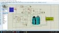
I'm working on my final year project mppt solar charge controller Arduino based with a buck converter, to charge a 12 volt 60ah lead acid battery from a 150w solar panel, 18.5v, 8.11A. I’m using proteus to design but it’s not working properly please I need helpHaving designed numerous MPPT battery chargers, have never had any reason to implement a boost stage prior to the buck circuit; its just inefficient and a waste of power. Unless you are using tiny PV 6v panels (toys) or something very small, I wouldn't recommend it.
For a battery charger the most important measure is charge current and battery voltage; for mppt the requirement is to measure the instantaneous charge current and attempt to maximize it for all levels of PV illumination by varying the buck PWM. At each charge current measure, note the battery end point voltage; when in in Bulk phase and that end point is reached then start a constant voltage timer and keep the voltage constant to allowing the current to taper, then switch to float. These settings being set by the battery chemistry.
I generally stay in MPPT mode as much as possible, but backing off as required depending on the dynamic loads on the battery bank under charge; - talking about large systems here perhaps powering a house etc.
If implementing some sort of pre-boost stage then fix it at times 2 or similar going into your buck stage, do your control in the buck aiming for max current.
Cheers
Mike
Attachments
-
 507.2 KB Views: 6


