basic transistor diff amp

Thread Starter

Zeeus

Joined Apr 17, 2019
616
Thought I was starting to understand basic transistor circuits

Someone please assist

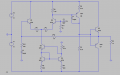
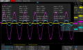
Made this circuit on breadboard and jumper wires (problem?) 1khz

Current source at bottom is providing about 2mA...So collector of Q6 should be about 9.8V right? but not the case...Collector is about 11.4V (fluctuates from about 10.45 - 11.6) and my psu is about 11.8v and Q8 needs about 0.6v

The base of Q3 about -0.01v but Q6 about -0.1v... Thinking this was the problem, removed the emitter resistors(to increase gain) and connected 18 ohms between the 2 bases then collector of Q6 became 9.8v like formula will predict...

But I do not want to connect the bases together!! how to fix? I am applying the signal directly to the base of Q6 without capacitor (is this okay?)

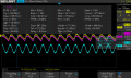
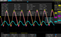
After applying signal, the gain changes...it can show gain of 100 (I bypassed R6 and used feedback at this point) now and 2mins later gain reduces or increases...

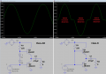
Thank you! and did not improve push-pull because author wants to show how feedback can improve distortion

I miss this site :(\

R9 : output resistor is 10k and I used transistor IC
 

Attachments

Thread Starter

Zeeus

Joined Apr 17, 2019
616
No, the gain will be equal to R12/R10. So if you want Vin = Vout (voltage follower) you need to remove R10 resistor.
Yeah right..sorry

look..first image is the circuit you posted... Used 470 for R10...output is funny

used 2nd image and get 3rd image but not in phase (think saw somewhere to expect phase difference with feedback) Although I did similar circuit last week and everything (gain, phase) was good

I think maybe connection problem because shape of output waveform changes by touching any wire

dunno :( :(

Thanks
 

Attachments

Jony130

Joined Feb 17, 2009
5,487
what should collector voltage of Q1 be? 24 - 0.7 yh?
It will be around Vcc - Vbe4
.Cap of c1 has negative side to ground yh??
Yes.

760 ohms was hot, changed it.
This resistor should never get hot. Try to add a 1nF capacitor between the Q4 base and collector.

First image with no emitter resistor at q4 then second image with 470 ohms at emitter of q4 then bypassed with cap
470Ω is way too big. If you add it into Q4 emitter you to need to change the Rc1 resistor value also to about 5.1kΩ.

(12-0.7)/4700 = 2A
No, wrong

Iee = (12V -0.7V)/4.7kΩ = 11.3V/4.7kΩ = 2.4mA Hence Ic1 ≈ 0.5*Iee
 
Last edited:

Audioguru

Joined Dec 20, 2007
11,248
How can your simulation work when the transistors have no part numbers?
I notice that your output transistors have no quiescent bias current so that they are in class-B and produce severe crossover distortion.
Negative feedback cannot eliminate the distortion, only reduce it.
Here is a simulation showing class-AB with a little bias current and your class-B:
 

Attachments

Thread Starter

Zeeus

Joined Apr 17, 2019
616
How can your simulation work when the transistors have no part numbers?
I notice that your output transistors have no quiescent bias current so that they are in class-B and produce severe crossover distortion.
Negative feedback cannot eliminate the distortion, only reduce it.
Here is a simulation showing class-AB with a little bias current and your class-B:
Thanks.. I did the circuit on the left at first, with 3 diodes and emitter resistors.. Reading AOE lab book and the author asked to do the right image to show how negative feedback can cure distortion "making the signal at base of push-pull do something magical"

Anyways, will add a Vbe multiplier circuit after seeing the magic
 

Thread Starter

Zeeus

Joined Apr 17, 2019
616
Yes, it can. But the NTE937 is faster so if you have a piece of bad luck the circuit may start to oscillate.


Try to build the simpler version
https://electronics.stackexchange.c...elimination-with-differential-transistor-pair
Didn't add :

Because negative feedback is applied, voltage at both base are equal. Then because c1 is there no dc current through and since base input impedance (what's value? Nvm) is high no much current into base of Q2 therefore Vout = 10v. .??????

With signal gain is 11 if open loop gain is but not really so gain 10


Will revisit this.. Thanks for link..re-reading...good to think early effect.
 

Thread Starter

Zeeus

Joined Apr 17, 2019
616
You screenshot shows R9 to be 10 Ohm.
You will have to make up your mind, is it 10 or 10,000?
Sorry it's 10k...

If it is 10 is it not bad? Output impedance from Q8 is about 6.2k... What is impedance of push pull with 10 ohm emitter resistor ?
 

Thread Starter

Zeeus

Joined Apr 17, 2019
616
Yes, it can. But the NTE937 is faster so if you have a piece of bad luck the circuit may start to oscillate.


Try to build the simpler version
https://electronics.stackexchange.c...elimination-with-differential-transistor-pair
Damn!! after sometime trying to figure out why smoke smell is coming out from this circuit : changed breadboard, rechecked connection 4 times..Finally found the IC had problem :( (china)

24V supply..12k for Rc2

Anyways, both bases have same voltage because of negative feedback and due to cap, voltage at output is same as voltage at bases

gain is about 11...output swing max +-6 from 12v quiescent....change in collector current of 3..change in Vb of 29mv
Collector current of Q4 from 0.5mA to 1.5mA

Possible to calculate change in collector voltage of Rc1 from the 29mv?
using average value of Re = 33 and voltage divider 29 = (Re + 680)*X/Re

I want to calculate the change in collector voltage of Q1 then find the change in base voltage. This change in base voltage will be the possible input swing correct?
 

Attachments

Top