Facebook
 Google
 GitHub
 Linkedin
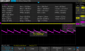
Hi..Trying to understand
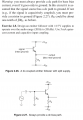
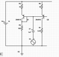
First image : Please explain more
Transistors are 2n3904 and 2n3906
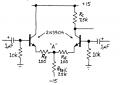
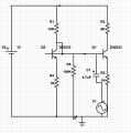
Anyways, I added this cap.. 2nd image : replaced the 6k (6.2k) with 4.7k to get 6v at collector...Gain : Rc/re around 240..re changes yeah but the gain I observed was about 50..why so??
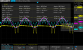
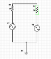
3rd image is same as first but with emitter resistors and did not change the 6.2k..6v at collector of Q1...Changing the cap (100k) to 4.7k put's collector of q1 at 7.4v..changing it to 1k sends collector to about 11v..The capacitor is there to take away current from the base?
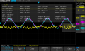
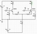
4th image : R4 and R7 are 150...If I remember correctly (not sure i checked : think i did), voltage at collector of q2 was about 6v... I used an IC with transistors CA3096...For the inputs, please look at 5th image : Is this okay to do? don't want to destroy my generator..So doing this get's the 6th image
Now one input to the differential amp was 1khz and the other was the sum of the two frequencies (1khz and 140hz)....7th image was the result
when I changed the inputs (1khz to the other side of amp and the sum of frequencies input to the other side)..8th image was result : was expecting this since the difference between the two inputs is the 140hz signal : This is how this amp should work right? but notice that the (sum of frequencies input) has changed shape
The 9th image : pnp transistors.I added the base bias resistor (not shown in image)....When I connected the signal input (I did not turn it on)..Connected scope probe to the input which is not turned on : The last image is the result : like lc ringing : what's happening?
Thank you thank you thank you
Just got LTSpice")
First image : Please explain more
Transistors are 2n3904 and 2n3906
Anyways, I added this cap.. 2nd image : replaced the 6k (6.2k) with 4.7k to get 6v at collector...Gain : Rc/re around 240..re changes yeah but the gain I observed was about 50..why so??
3rd image is same as first but with emitter resistors and did not change the 6.2k..6v at collector of Q1...Changing the cap (100k) to 4.7k put's collector of q1 at 7.4v..changing it to 1k sends collector to about 11v..The capacitor is there to take away current from the base?
4th image : R4 and R7 are 150...If I remember correctly (not sure i checked : think i did), voltage at collector of q2 was about 6v... I used an IC with transistors CA3096...For the inputs, please look at 5th image : Is this okay to do? don't want to destroy my generator..So doing this get's the 6th image
Now one input to the differential amp was 1khz and the other was the sum of the two frequencies (1khz and 140hz)....7th image was the result
when I changed the inputs (1khz to the other side of amp and the sum of frequencies input to the other side)..8th image was result : was expecting this since the difference between the two inputs is the 140hz signal : This is how this amp should work right? but notice that the (sum of frequencies input) has changed shape
The 9th image : pnp transistors.I added the base bias resistor (not shown in image)....When I connected the signal input (I did not turn it on)..Connected scope probe to the input which is not turned on : The last image is the result : like lc ringing : what's happening?
Thank you thank you thank you
Just got LTSpice
Attachments
-
 183.8 KB Views: 24
 -
 88.5 KB Views: 25
 -
 91.8 KB Views: 23
 -
 102.1 KB Views: 23
 -
 55.7 KB Views: 20
 -
 38 KB Views: 22
 -
 35.4 KB Views: 21
 -
 31.7 KB Views: 21
 -
 102.1 KB Views: 22
 -
 90.9 KB Views: 23