Basic amplifier theory not working in practice.

Thread Starter

Chowderdork

Joined Dec 12, 2021
5
Hi all. Newbie. First the disclaimer that apparently I don't learn like normal people do, or so the brain folk tell me - although I'm now in the twilight of what has been a swimmingly half century technical career. I learn by doing, not reading how to do - not that I find no value in the latter; but "remove bolt A" is 'what' .. real world under a bus in minus twenty with bolt A having been subjected to 15 years of road salt is 'how'. I also don't tend to 'get' what I read until I see it - or do it - in real life. That said:

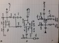
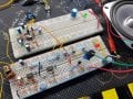
So I've been playing with breadboarding low power amplifiers .. Electret mikes through 741's, simple class A common emitters with 2SC945's and 2N3904's .. today a P-P with a '945 and 2SA733.

All seem to work - and yet none do as expected. There's something I'm missing between what my scope, ears, and what the manual is telling me.

(one) test signal is also a breadboarded Wien bridge sine wave "classic" oscillator using a 741 and 7660 (for negative supply), outputting a relatively clean waveform. Asterisk .. more on that in a second.

My first experiment was to AC couple the sine wave (1.0V p-p) through a CE class A amplifier circuit with values found on the internet, and substitute the various resistor values with multi-turn pots and observe the changes in the output waveform. Agian, this is how I learn what the bits actually do. I've seen a lot of industry folk over the years who knew how to swap something out, but couldn't tell you why.

Now every text I've ever read showed the input amplitude wee, and the output an awesome order of magnitude. This has not been my breadboard experience this last week. And I have yet to find component values in any of a score of published circuits that actual;l;y do this.

Either pretty waveform transfers, OR amplitude (and even that, not much) .. but never both. I'm not certain what I'm doing wrong .. especially as everything that I've built will happily drive a 4 Ohm speaker with decent sounding audio .. but I can't seem to achieve that textbook voltage gain diagram and I don't know why.

My goal is not a guitar amp, or any one thing in particular, but to understand how to amplify an analog signal with fidelity. Sine in, sine (inverted or not) with greater amplitude out.

This should not be so difficult.

So what am I asking for? Well .. it's quite possible that you all know exactly what I'm missing and are chuckling at the moment - so that clue would help, lol. Otherwise, a known good single stage ultra clean class A common emitter amplifier schematic using discreets .. something say around 50 mV in, 3 V out that I can study and dissect.

Second, that asterisk .. My scope (set 500mV/Div) says my 1KHz sine wave is 1V p-p .. My RMS DMM set at 20VAC says it's 2. Hundred percent disagreements 'tween the two have me scratching my head.

Any help appreciated.

CD.
 

BobTPH

Joined Jun 5, 2013
8,967
You are overloading the circuit with you 4Ω speaker. It takes a power amp to drive a low impedance speaker, and it does not sound like that is what you are building. A simple 1 transistor class A amp can have a gainf about 200, but not to a 4Ω load.

Show us a schematic of one of your failing circuits.

Bob
 

BobTPH

Joined Jun 5, 2013
8,967
Here you go. Two copies of the same 1 transistor amplifier.

The one on the left has a 100K load, output is blue. The one on the right has a 1K load, output is green. If you go to a 4 Ohm load, the line looks flat on this graph. Input is 10mV peak.

1639338210573.png
 

Papabravo

Joined Feb 24, 2006
21,225
Your title is misleading. Basic amplifier theory is working just fine. It is your incomplete understanding that is the problem.

I suppose one could learn to design and analyze circuits without reading, but it sounds like a heavy lift if you have to do it all by yourself. I know you have trouble reading things, but can you write out a series of arithmetic steps to solve a problem? Without that capability I'm afraid your further education in electronics is going to be limited. Not knowing about the impedance of a load, is a hole you could drive a mining truck through.
 

sghioto

Joined Dec 31, 2017
5,390
I would like to see one of the circuits that you have built that will drive a 4 ohm speaker. Not being derogatory just curious.
 

Audioguru again

Joined Oct 21, 2019
6,692
The little Oriental output transistors have a maximum allowed output current of only 100mA and work poorly above 50mA. Then the maximum peak voltage into a 4 ohm load is 0.05A x 4 ohms= 0.2V but the class-A also needs plenty of current then the maximum peak output voltage in a 4 ohm load might be only 0.1V.
 

Papabravo

Joined Feb 24, 2006
21,225
A class B stage, using power transistors, could do the job. Designing such an amplifier is far from a trivial enterprise. Also a class D amplifier can do it, but that would be even more of a challenge for the TS. I have read numerous pieces on class D amplifiers but have no intuitive sense about how I would go about such a design except more reading and simulation and building and testing.....wash, rinse repeat. I think the TS is SOL.
 

Thread Starter

Chowderdork

Joined Dec 12, 2021
5
Wow.. That's a lot of help. Let me reply in turn.

First the 4 Ohm load is misleading. I only used a speaker as an output on one circuit that I took from here: figure 6-B. Just to see if it worked.

https://www.nutsvolts.com/magazine/article/bipolar_transistor_cookbook_part_7

It does actually work, so far as producing audio, (odd now that I look again, I clearly misread the output cap value and only used 10 uF in mine) but an audio power amp is not strictly my goal. And yes, the loaded output is indeed just about what Audioguru predicted. I'm not interested yet in perusing 'this' topology, focusing first on how a single transistor behaves in the linear region.

Sghioto: most of what I've been experimenting with has been this:

https://www.electronics-tutorials.ws/amplifier/amp_5.html.

Using various base values from published circuits, and tweaking the values. For example starting with 220 Ohms on the emitter and 1.2 K B-E, then pots on the collector and B-C, tweaking about while observing the changes, watching the output clip, distort, etc on the scope.

" It is your incomplete understanding that is the problem. " Lol, yes.

Hmm .. So load impedance. The majority, save for the one 4 Ohm experiment, has been what I assumed to be no load - just the scope input.

FWIW, It's not that I can't read, Indeed almost the opposite. I more easily understand an explanation rather than the math, although I have been going through the latter.

BobTPH, thanks for those.

Thanks everyone, I'll continue with the tinker.

CD.
 

Thread Starter

Chowderdork

Joined Dec 12, 2021
5
Here is generally what I'm playing with.

On the board, I mis-spoke. The output is complimentary pair not push-pull, but again - this isn't what I'm interested in yet.

I have a working sine wave generator, top board, and below a mic and 741 preamp that I'm using as signal sources.

Schematic bottom is where I've been experimenting with 2SC945 and 2N3904 transistors.
 

Attachments

Thread Starter

Chowderdork

Joined Dec 12, 2021
5
Ah, I think I may have a handle on that mining truck.

As I understand the purpose of each resistor. The emitter R offsets the output so that the tranny can output a complete sine above the ground rail. The collector is a pull up for the positive half of the wave as well as current limiting and setting the output 'power'. The base divider biases the transistor into the linear range. BUT .. if the values are too low the base appears a heavier load to the previous stage .. so my problem may not be low output (I do seem to be getting a smaller output signal than input), but that I'm actually loading the input? So in theory, much larger base bias values should also increase output amplitude?
 

BobTPH

Joined Jun 5, 2013
8,967
No, the emitter resistor provides negative feedback to the biasing circuit to keep it stable. It is not strictly necessary.

And you are right about the biasing resistors, increase them by a factor if 10, then adjust the pot until the collector is at half the supply voltage.

If you just randomly adjust the pots it is unlikely you will ever hit a working configuration.

Bob
 

Thread Starter

Chowderdork

Joined Dec 12, 2021
5
Thanks. The collector tip is helpful. FWIW, I haven't been two fisting the pots willy-nilly. I've tried to be somewhat methodical playing with published circuit values and recording how changes alter the signal. I've actually "discovered" quite a bit, that although I've likely read it in the past .. once seen, makes better sense.

Hmm .. didn't know that about the emitter R. I'll have to read up on that. I assumed it's function something other .. recently was playing with a 6E5 eye tube, and had to bias the cathode so I could drive the grid negative with respect.

All of your replies have been quite helpful.

Can't wait to get back to the bench again .. but first the work week ahead.

CD.
 

MrChips

Joined Oct 2, 2009
30,809
Here is how to design with transistors, one step at a time.
You need to pay attention and work within the limitations of your components.

1) Begin with your supply voltage. Choose what ever voltage you want and have readily available.
Let us assume that your voltage supply is a 9V PP3 battery which is readily available.

1639360746068.png
1639360858437.png

You will need a 9V battery clip to connect to the battery. Red wire is positive, black wire will be GROUND.

2) Select a general purpose NPN transistor such as 2N3904.
1639360813334.png

3) Choose a load resistor while giving considerations to the limitations of the transistor and the supply voltage.

We want half the supply voltage (i.e. 4.5V) across the load resistor.
The 9V battery cannot comfortably supply more than 50mA
If we allow the transistor to conduct 1/10 of that, say 5mA, the required load resistance R = V / I = 4.5V / 5mA = 900Ω.
Let us simplify things and make R = 1kΩ

At this stage in the game you can forget about putting a load such as a loudspeaker at the output. You are just learning how to set up an NPN transistor to provide voltage gain.

This is what we have so far.
2N3904.jpg
4) Now we need to bias the transistor and apply an input signal.

We need to make sure that we do not upset the DC bias. For this, we couple the input signal via a DC blocking capacitor, i.e. a high-pass filter. A 1-10μF capacitor will do.

For the transistor bias, we will do what you are so accustomed to do. We will use a variable resistor of about 1MΩ.
We need to limit the minimum resistance to avoid blowing the transistor. Hence we insert a series resistor to set the minimum resistance.

Here is your first test circuit:

2N3904_2.jpg

5) Now we can play around with this. Input a very low amplitude sine wave, in the millivolt range and examine the output on the oscilloscope. Adjust the DC bias and observe the behavior of the circuit. When you find a sweet spot where the output is balanced between the supply rails without clipping, remove the pot and measure it’s resistance. Now, if you wish you can replace the pot with a fixed resistor.

Measure the circuit gain = Vout / Vin. (Use peak-to-peak voltages as seen on the oscilloscope. Forget the AC voltmeter for this. I will explain this later.)

This is not the world's greatest circuit. I will tell you why. One step at a time.
In the next step I will show how to improve on this circuit.
 

MrChips

Joined Oct 2, 2009
30,809
In order to understand the discrepancy between the oscilloscope wave and the AC DMM measurement, let us look at some terminology and definitions.

1639409629134.png

Peak-to-peak voltage is the total range between maximum and minimum voltage.
For a sinusoidal waveform that is symmetrical about 0V, peak-to-peak voltage is twice the amplitude.

The diagram above shows a sine wave of 1V amplitude and 2V peak-to-peak.

RMS stands for Root-Mean-Square. Regardless of the shape of the waveform, AC or DC, the RMS value is the value of a DC signal that will produce the same heating effect.

For a sinusoidal waveform, the RMS value = amplitude x 0.707
Thus, the RMS value of a 1V sine wave is 0.707V.
The conversion factor is different for different wave shapes.

By definition, the RMS value of a 1VDC signal is 1V.

In your situation, it would help if we knew the make and model of your DMM as well as the oscilloscope.
Are you using the scope probe in the x10 position? (which is what you should be doing.)

You reported a 1kHz sine wave showing 1V p-p on the oscilloscope. This represents an amplitude of 0.5V.
The RMS value is 0.5V x 0.707 = 0.35V

This is not in agreement with the DMM reading of 2.

Honestly, we don't know the reason for this discrepancy. What we do know is that voltmeters do not always report RMS values correctly. The method used to determine RMS is highly affected by frequency. Many meters are calibrated at AC line frequency, 50-60Hz. Some meters state True RMS in their specifications. This is still questionable.

The bottom line is, don't rely on your AC DMM to show correct RMS value. Use your oscilloscope instead.
 

MrChips

Joined Oct 2, 2009
30,809
The importance of input and output resistance (or impedance)

A perfect amplifier would have the following characteristics:

1) infinite or very high input resistance
2) zero or very low output resistance
3) infinite or very high voltage gain
4) infinite or very high bandwidth

Let us take one at a time.

1) High input resistance means that the amplifier will take very little current from the input source. It will not distort or reduce the amplitude of the input signal. This also means that it must have low input capacitance (which is the impedance part).

Ohm's Law, I = V / R

If R is large, input current I will be small.

2) Low output resistance means that the amplifier can output a lot of power.

Power = V x I = V x V / R

If R is low, output current and power will be high

3) High gain means that it can amplify a small signal to drive a lot of power. An amplifier with a gain on 1,000,000 will take a 10μV signal and output 10V.

4) High bandwidth means that the amplifier can amplify signals at any frequency with high fidelity, i.e. low distortion.

The bottom line is, you need to match the input and output resistance of the amplifier with your application.
An amplifier with 100Ω output resistance is not suited to drive an 8-ohm speaker.
 
Top