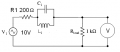
Band stop filter

Thread Starter

Jonathan Bell

Joined Jan 4, 2008
2
Why would the output voltage of a bandstop filter be higher than the supply voltage when not at resonant frequency?

For example a bandstop filter is used where a supply of 10v is used. A resistor of 200ohms is put in series with the filter. Resonance is at 7kHZ and gives an output of 516mV. However at 1kHZ the output is 11.7V. How can this be when the source is only 10V?

Thanks
 

Thread Starter

Jonathan Bell

Joined Jan 4, 2008
2
The attached picture show an example of the very simple filter in use. L1 and C1 are unknown as the filter was given as an invistagation. The output voltage was taken across the load resistor. The question is why would a reading of 11.7V be taken when th source is 10V.
 

Attachments

scubasteve_911

Joined Dec 27, 2007
1,203
Wouldn't this be because the tank circuit is acting like a storage element with a voltage potential in series with a DC supply ?

That's my guess anyways

Steve
 

Ron H

Joined Apr 14, 2005
7,063
The attached picture show an example of the very simple filter in use. L1 and C1 are unknown as the filter was given as an invistagation. The output voltage was taken across the load resistor. The question is why would a reading of 11.7V be taken when th source is 10V.
Is this a simulation, or hardware? How are to measuring the source and the output?
You must have had some actual values of L and C if you got measurements. Or is this a homework problem, and you are supposed to explain the hypothetical results?
 

cableboy70

Joined Jan 11, 2008
3
Not sure...maybe its because the interaction between inductor and capacitive reactance...with the present of resistive component ? (the 200ohms resistor)
 
Top