Back to basics - BJT transistor BC547B (Solved)

Thread Starter

PsySc0rpi0n

Joined Mar 4, 2014
1,762
You so not show a schematic for the circuit (post #59) on your breadboard with a BC547B transistor with a 5.02mA collector current and a bunch of series resistors at the base with a total of 50.78k. The voltage feeding the resistors is unknown and how can the beta of the BC547B be only 100?
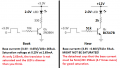
Didn't I say I was following the book example? So, the schematic is the same. The only thing missing is the input voltage at the base which is 3.3V.
 

LvW

Joined Jun 13, 2013
1,756
PsyScOrpiOn, don´t misinterprete the quantity "beta" in switchinng operation (saturation).

What is the condition of saturation? Answer: Vce<Vbe, which means: The B-C pn junction is forward biased!
Hence, we need collector current which is so large, that the voltage drop across Rc is so large, that Vce falls below the mentioned threshold.
Because the transistor is a voltage-controlled device, the voltage Vbe must have a value which can allow this large value for Ic.

Now comes a practical aspect for designing the switching stage (because nobody knows if we need Vbe=0.7 or Vbe=0.72 volts):
Because the B-C junction is forward biased, the base current is much larger than under "normal" conditions - and THIS fact is a good INDICATION for saturation. As a rule of thumb we know that as a minimum the base current should be in this case 10% of the collector current.
THIS is the real reason for the fact that we design the stage for a (ficticious) "current gain" (beta) of 10. And because such a stage - in many cases - works with an input between (nearly) 0V and some volts (V_on=5V), we are using not a voltage divider at the base but a series resistor RB, which is designed according to Ohms law:
RB=(V_on - 0.7)/Ib with Ib=Ic/10.
(As you can see, in this equation it does not matter if we insert V_be=0.7 or =0.72 volts because with beta=10 (or even smaller) we are on the "safe side").
 
Last edited:

Thread Starter

PsySc0rpi0n

Joined Mar 4, 2014
1,762
Now comes a practical aspect for designing the switching stage (because nobody knows if we need Vbe=0.7 or Vbe=0.72 volts):
I don't understand your statement:

- > Nobody knows if we need Vbe= 0.7V or Vbe = 072V??

What you mean with need ?

I used the value the datasheet says.

As for the rest of your reply, that's exactly what I did.
Started by setting Ic = 5mA.
Calculated Rc for the 5mA current. Then, I designed the ficticious stage to be 1% of Ic instead of 10%, as you suggest (this is actually the only difference).

So, for Ib = Ic/100, I would have

Rb = (3.3V - 0.65V) / (5mA / 100) = 53kΩ
 

LvW

Joined Jun 13, 2013
1,756
I don't understand your statement:

- > Nobody knows if we need Vbe= 0.7V or Vbe = 072V??

What you mean with need ?
May I repeat what I wrote?
"..the voltage Vbe must have a value which can allow this large value for Ic.
Now comes a practical aspect for designing the switching stage (because nobody knows if we need Vbe=0.7 or Vbe=0.72 volts)"

That means, of course: We do not know the exact value for Vbe which is needed to allow the desired collector current Ic=f(Vbe).
Therefore, we use an estimate (0.65 or 0.7 volts, for example) and use a sufficient safety margin for calculating the base resistor Rb=(V_on - 0.7)/Ib with Ib=0.1*Ic or even larger.

Question (to your design): Why do you use a base current which is 1% of Ic only?
Do you want to ignore the fact that the B-C junction must be forward biased in saturation?
 

Thread Starter

PsySc0rpi0n

Joined Mar 4, 2014
1,762
May I repeat what I wrote?
"..the voltage Vbe must have a value which can allow this large value for Ic.
Now comes a practical aspect for designing the switching stage (because nobody knows if we need Vbe=0.7 or Vbe=0.72 volts)"

That means, of course: We do not know the exact value for Vbe which is needed to allow the desired collector current Ic=f(Vbe).
Therefore, we use an estimate (0.65 or 0.7 volts, for example) and use a sufficient safety margin for calculating the base resistor Rb=(V_on - 0.7)/Ib with Ib=0.1*Ic or even larger.

Question (to your design): Why do you use a base current which is 1% of Ic only?
Do you want to ignore the fact that the B-C junction must be forward biased in saturation?
Ok, so this 10% is a thumbs up rule, yes?
But the procedure is correct, right?

Set needed Ic, calculate Rb for saturation mode, taking into account that Ib = 10% IC, checking the datasheet for typical value of Vbe. <-- Is this correct?
 

Jony130

Joined Feb 17, 2009
5,488
In typical application any base current large than:

\( \Large I_B > \frac{\frac{V_{cc}}{R_c}}{\beta_{min} } \) will saturate the BJT.

But for any real-world transistor, the β is not constant. Beta varies with Ic, Vce, temperature. And what is worse, every single transistor will have a different beta value.

Thus, to overcome this problem with beta and saturation we overdrive the base with a much large base current, we simply increase the base current well beyond:

\( \Large I_B > \frac{\frac{V_{cc}}{R_c}}{\beta_{min} } \)

We do this to make sure that we have enough base current to put the transistor well into saturation for every condition we have in our circuit.
Additional most BJT's vendors define saturation region when Ic/Ib = 10 (called Forced Beta). And the most datasheet show Vce_sat for Ic/Ib = 10
So, to be one hundred percent sure that your BJT will be in the saturation region you must use this so-called "forced beta" technique when choosing base resistor value.
Thus the typical forced beta value should be around 10...50. So there is nothing special about the "10" number.

The transition from active region to saturation region is not abrupt. Most manufacturers use 10 as the value of beta at which they characterize the saturation behavior of their transistors simply because that is the convention that evolved decades ago and because adhering to it makes comparing transistors a lot easier. But you can use whatever value of beta you want. Choose it too high and you are too far into the active region to be able to force the beta in a well controlled fashion. Choose it too low and you waste excess power in the base-emitter junction in exchange for basically no improvement in Vcesat. Remember, a big part of the reason for operating in saturation is to minimize power dumped in the transistor. But since the Vbe is now a few times the Vce, you want to keep Ib as low as you can consistent with other goals. Running deep saturation also increases the charge that has to be removed to bring it out of saturation which slows down the switching speed.
And remember that the transistor going into saturation isn't a property of the transistor itself, but instead a property of the circuit surrounding the transistor and the transistor, as part of it.
See the example here:

untitled.PNG

Co you solve for Ib, Ic, and Vce? And determine whatever the BJT is working in the active region or in the saturation region.
 
Last edited:

LvW

Joined Jun 13, 2013
1,756
Ok, so this 10% is a thumbs up rule, yes?
But the procedure is correct, right?

Set needed Ic, calculate Rb for saturation mode, taking into account that Ib = 10% IC, checking the datasheet for typical value of Vbe. <-- Is this correct?
For which purpose you want to check the datasheet for "typical value of Vbe" ?
Example: Second circuit as given by Jony130.
Ib=(12-Vbe)/47k.
Do you think that it is important if Vbe=0.7V or 0.75V - knowing that the 47k resistor is selected arbritrarily as 10% of 470k??
 

Audioguru again

Joined Oct 21, 2019
6,691
To be a switch, you want a transistor to saturate with a very small Vce. The BC547 saturates well when its base current is 1/20th its collector current. Its beta is when it is far from saturation when its Vce is 5V.
The transistor in the book and your transistor are not saturated.
Look here what you made on your breadboard:
 

Attachments

crutschow

Joined Mar 14, 2008
34,428
Do you imply that the 2N3904 beta will be lower than this?
No, the implication is that the value of beta is of no interest when taking about saturation.
As has been said many times, the linear beta value of a transistor is not used when the transistor is operated as a switch and taking about beta for that use is a red herring.

To use a transistor as a switch the base current should be 1/10th to 1/20th of the collector current.
It's sometimes stated that this is using a forced beta of 10 or 20, but that has no particular relation to the beta of the transistor in linear operation.
Look at any BJT data sheet.
The value for beta is stated at a Vce of several volts (linear region), not for a low saturation voltage.
 

MrChips

Joined Oct 2, 2009
30,806
This is a good exercise to learn how BJT circuits work.

1618330030638.png

I tested this with real components. The transistor I used is 2N3904.
How would I know what value of β to use in the calculation?

Circuit on the left
I will firstly assume that VB = 0.7V
IB = VB / RB = ( 12 - 0.7) / 470k = 24μA

If I were to assume β = 100
Ic = β x IB = 100 x 24μA = 2.4 mA
Vc = 12V - 2.4V = 9.6V

The tested circuit showed the following:
VB = 0.75V
Vc = 8.1V

Working backwards, had I selected β = 160
Ic = β x IB = 160 x 24μA = 3.8 mA
Vc = 12V - 3.8V = 8.2V

(The value of β as measured on a DVM was 156).

Circuit on the right
I will firstly assume that VB = 0.7V
IB = VB / RB = ( 12 - 0.7) / 47k = 240μA

If I were to assume β = 100
Ic = β x IB = 100 x 240μA = 24mA
But this cannot happen because the max load current is 12mA.
Hence the BJT must be in saturation mode.

If I were to assume that VCE = 0V
current gain = 12mA / 0.24mA = 50

The circuit as tested showed
VB = 0.8V
Vc = 0.17V

The take away here is that if the BJT is operating in the linear region the value of β at that Ic would be close enough.
If the BJT is outside of the linear region then all bets are off as to what value of β to use in your calculation.

From ON Semiconductor 2N3904 data sheet, shows current gain just under 150 at Ic = 4mA.
2N3904 current gain.jpg
 

Audioguru again

Joined Oct 21, 2019
6,691
Notice that the beta of 150 at a collector current of 4mA is when it is far from saturation with a Vce of 10V.
The graphs in a datasheet are for a "typical" one. The text is a guarantee that even a weak but passing one saturates well when its base current is 1/10th its collector current. Edited the current.

The transistor in your breadboard test was lucky to be more sensitive than minimum.
Nobody sells "typical" or better transistors. All you buy might be minimum or only slightly better.

I always design circuits for "worst case" (lowest spec's) so that every circuit I make works perfectly.
 
Last edited:

Thread Starter

PsySc0rpi0n

Joined Mar 4, 2014
1,762
With all these, I'm lost.
I understand that we can only look at beta when we already know the transistor is at linear region. And I mean, look at beta, not to use it for any calculation but only as a means of saying that at a particular situation, the transistor is amplifying Ib current beta times.

But I'm still confused to how to find the resistor values for a specific scenario. If the procedure I did is wrong, because I used beta to find Ib, then, that saying (so to speak) of 1/10 to 1/20 of Ic, will put any transistor in saturation mode? If not, what else do I need to think about to put a transistor at it's saturation mode?

(going to do the math again for 1/20 of Ic current for my BC547B an try it on the breadboard).

And, btw, @MrChips , that circuit isn't the same. So, I don't want to compare it to the one we are discussing right now!
 

Thread Starter

PsySc0rpi0n

Joined Mar 4, 2014
1,762
Anyway, I just tried the procedure of choosing Ib = Ic/10. Now, I'll try different transistors to see if the differences are significant or not.

Edited;
I tried one BC548B and one 2n2222a. Current values of Ib and Ic didn't change much.
 

MrChips

Joined Oct 2, 2009
30,806
You have selected a random circuit and are trying to solve for current and voltage.
I think you have bitten more than you can chew.

There are two different scenarios:
1. How to solve for current and voltage in a circuit?
2. How to select component values when designing a circuit?

Let's take two simple examples of case #1.

Example #1
Given the following circuit, solve for Vout in terms of R1, R2, and Vin.
1618344170261.png

This is doable because it is a linear circuit with linear equations.

Example #2
Solve for current I and VR.
1618344324531.png

This is may look simple but it is not. The LED equation is nonlinear with some unknown parameters.
You would need to characterize the diode in order to solve this.
 

Thread Starter

PsySc0rpi0n

Joined Mar 4, 2014
1,762
I understand that. And this circuit was not a random circuit. I was reading through the book and trying the examples while I was reading.
 

LvW

Joined Jun 13, 2013
1,756
But I'm still confused to how to find the resistor values for a specific scenario. If the procedure I did is wrong, because I used beta to find Ib, then, that saying (so to speak) of 1/10 to 1/20 of Ic, will put any transistor in saturation mode? If not, what else do I need to think about to put a transistor at it's saturation mode?
No - I am afraid there is still a misunderstanding on your side. You cannot start with Ib.
(1) First and most important condition for saturation:
Ic is so large that most of the available voltage appears across the collector resistance - hence, only a mimnimum remains for Vce (0.2 V app).
With other words: Vce<Vbe (app. still 0.7..0.75 V)

(2) How can we be sure that this condition is fulfilled?
Answer: Because the B-C junction must be forward biased (because of Vce<Vbe) the base current Ib is much larger than expected for linear application. This is the RESULT from the above considerations and a good and safe indication for saturation.

(3) Circuit design: Starting with the current Ic (as mentioned above under (1) ) you calculate the resistor RB for a base current Ib that is at least - let`s say - 10% of this Ic value.
(That means: 10% of that Ic which brings the transistor into saturation !!)
 

Thread Starter

PsySc0rpi0n

Joined Mar 4, 2014
1,762
No - I am afraid there is still a misunderstanding on your side. You cannot start with Ib.
(1) First and most important condition for saturation:
Ic is so large that most of the available voltage appears across the collector resistance - hence, only a mimnimum remains for Vce (0.2 V app).
With other words: Vce<Vbe (app. still 0.7..0.75 V)

(2) How can we be sure that this condition is fulfilled?
Answer: Because the B-C junction must be forward biased (because of Vce<Vbe) the base current Ib is much larger than expected for linear application. This is the RESULT from the above considerations and a good and safe indication for saturation.

(3) Circuit design: Starting with the current Ic (as mentioned above under (1) ) you calculate the resistor RB for a base current Ib that is at least - let`s say - 10% of this Ic value.
(That means: 10% of that Ic which brings the transistor into saturation !!)
@LvW I think you better start reading the posts until the end. I didn't start with Ib ever. I started with Ic and then used beta. But later, I fixed that approach and did the 10% thumb up rule. I even checked with different transistors and confirmed that current values didn't change by much.

Now, I will try to understand how to put them in cut-off state. I know there are some conditions that needs to be met in order to put it in the cut-off zone, so, I'll digg about that a little bit and then, I'll ask questions here.
 

Audioguru again

Joined Oct 21, 2019
6,691
A transistor is cutoff when it has no base current, then it does not conduct any collector current.
A transistor as a switch is cutoff when its emitter is at 0V and its base signal voltage goes to near 0V.
 
Top