Facebook
 Google
 GitHub
 Linkedin


First, it would be nice to have a manual for the 2834, if not a service manual or schematic. Maybe it is another Japanese model re-badged.
Anyway, just bought it used and seems to have some weird issues.\
The voltage selector was correctly set to 115VAC.
None of the fuses were blown. And a loud beep sounds at turn on.
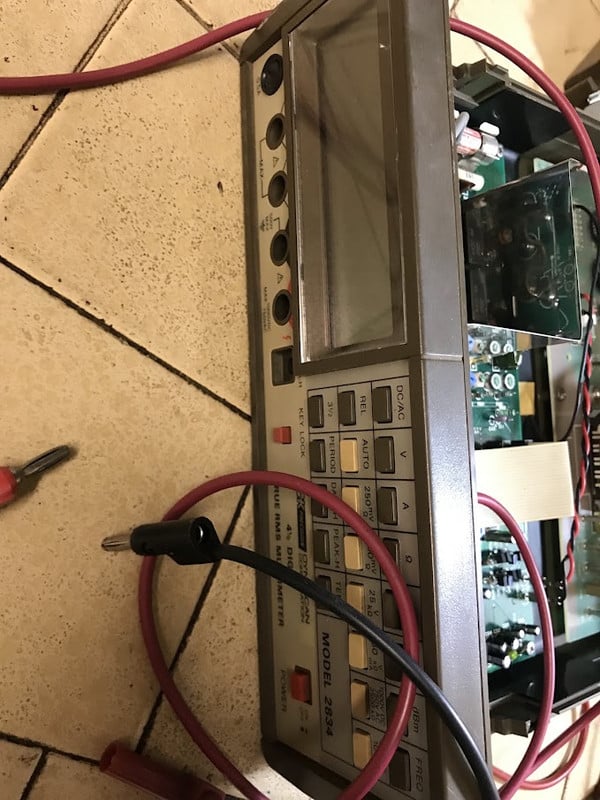
It powered up okay, with clear LCD digits, and seems to toggle switch presses okay, shifting from modes and ranges. I have not test most functions with metric tests (freq, voltages, etc). This might take a while to go thru.
HOWEVER: The default Auto resistance reads about 136.00 ohms (should be infinity or O.L). If I short the leads, I do get zero (or beep). I can get accurate R readings in Manual mode. And in Manual mode, the correct "OL" displays with open leads.
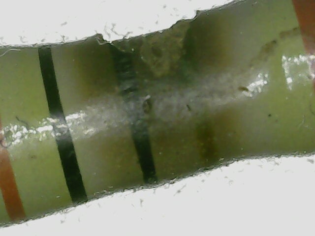
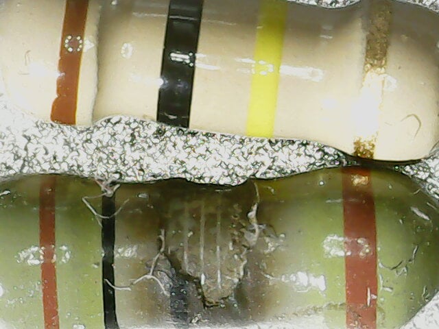
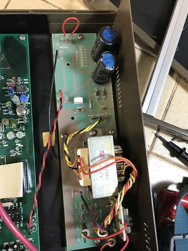
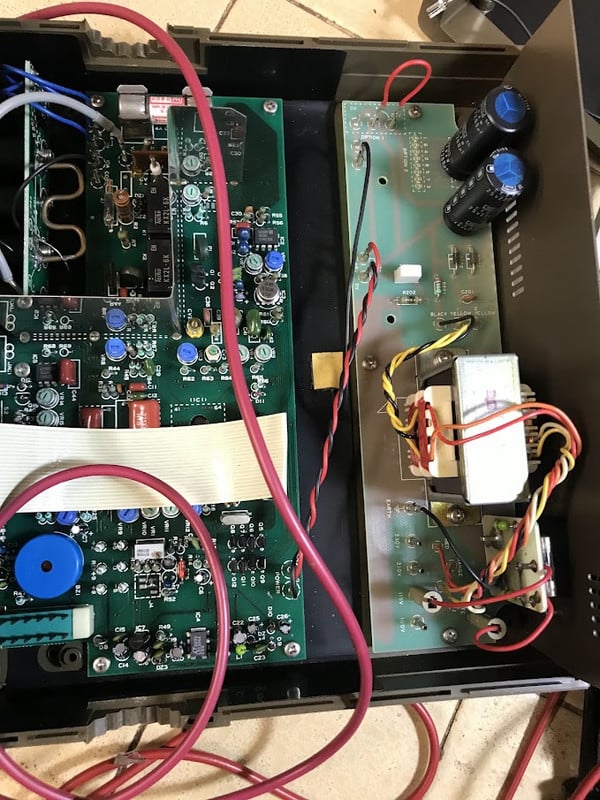
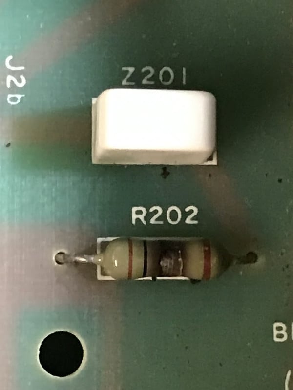
One of the power supply R's (R202 , see photo) was charred a bit and reading about 90k to 106k. The color code seems to suggest only 20 ohm.
I checked the the voltage at the main and PSU PCBs where there is a label: +9v/0v . I read about the 13.5vDC with the wires connected or disconnected to main PCB. I replaced the R202, but the 9v/0v rail still reads 13.5vDC. The mains rect caps (2200uF are both in excellent shape). No fuse is blown and all the other interior components, besides R202, APPEAR to be ok.
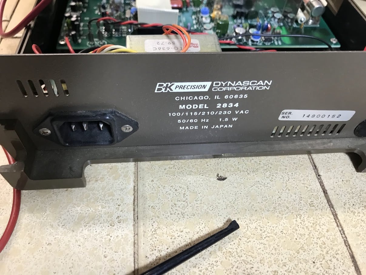
The unit consumes the 1.5W printed on the chassis rear.
Again, I don't have manual . much less service manual. So I appreciate any help if you have PDF copy!
Anyway, just bought it used and seems to have some weird issues.\
The voltage selector was correctly set to 115VAC.
None of the fuses were blown. And a loud beep sounds at turn on.
It powered up okay, with clear LCD digits, and seems to toggle switch presses okay, shifting from modes and ranges. I have not test most functions with metric tests (freq, voltages, etc). This might take a while to go thru.
HOWEVER: The default Auto resistance reads about 136.00 ohms (should be infinity or O.L). If I short the leads, I do get zero (or beep). I can get accurate R readings in Manual mode. And in Manual mode, the correct "OL" displays with open leads.
One of the power supply R's (R202 , see photo) was charred a bit and reading about 90k to 106k. The color code seems to suggest only 20 ohm.
I checked the the voltage at the main and PSU PCBs where there is a label: +9v/0v . I read about the 13.5vDC with the wires connected or disconnected to main PCB. I replaced the R202, but the 9v/0v rail still reads 13.5vDC. The mains rect caps (2200uF are both in excellent shape). No fuse is blown and all the other interior components, besides R202, APPEAR to be ok.
The unit consumes the 1.5W printed on the chassis rear.
Again, I don't have manual . much less service manual. So I appreciate any help if you have PDF copy!
Last edited by a moderator: