 Facebook
 Google
 GitHub
 Linkedin
Hi everyone, a microcontroller novice here (although an IT engineer and a long time lurker in this forum), trying to finish his first serious project.
I connected a small encoder to an Arduino Uno, displaying values on a 7 segment display via MAX7219. I wanted to transfer the system to a breadboard circuit based on Attiny 88 which would run ATTinyCore, but I got stuck uploading the code via Arduino IDE running the "Arduino as ISP" sketch from examples coming with Arduino IDE. Each attempt ends up with the message "avrdude: Device signature = 0x000000". I've also tried uploading the blink example, as well as reading the fuse values from the microcontroller from command prompt AVRDude, each time with similar outcome - all the values which were supposed to be meaningful (such as "Expected signature for ATtiny88 is 1E 93 11") end up being 0 (avrdude.exe: Device signature = 0x000000). Trying to read fuses' values from the chip ends up with the same result: all the values are displayed as being 0x00.
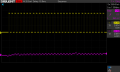
I tried the scope on the SCK, MOSI and MISO signals while issuing commands, and while SCK and MOSI have the proper swing with the correct 5V amplitudes, MISO amplitudes are way too small (some 0.2V), of course, provided that MISO pin from attiny88 generates the correct response to the commands issued in the first place. They are also very weird, meaning that the base value seems to be negative (cca. -0.2V) and they have severa values instead of just one, each 0.2V apart. I am attaching several screenshots. I have three Attiny88 chips and they all behave identically. They were sourced online from ebay, so it crossed my mind that they could be counterfeit.
I tried the same procedure with one Attiny85 chip, and it all worked as it was supposed to from try one, scope traces of all signals being as expected, and blink example working.
Did anyone have the same or similar experience? Does anyone have any idea what causes this and what could I try next? Should I give up and proclaim those chips broken? Or maybe try the HV programming procedure to try "rebooting" them (in which case I should first get a programmer)?
Thanks in advance!
I connected a small encoder to an Arduino Uno, displaying values on a 7 segment display via MAX7219. I wanted to transfer the system to a breadboard circuit based on Attiny 88 which would run ATTinyCore, but I got stuck uploading the code via Arduino IDE running the "Arduino as ISP" sketch from examples coming with Arduino IDE. Each attempt ends up with the message "avrdude: Device signature = 0x000000". I've also tried uploading the blink example, as well as reading the fuse values from the microcontroller from command prompt AVRDude, each time with similar outcome - all the values which were supposed to be meaningful (such as "Expected signature for ATtiny88 is 1E 93 11") end up being 0 (avrdude.exe: Device signature = 0x000000). Trying to read fuses' values from the chip ends up with the same result: all the values are displayed as being 0x00.
I tried the scope on the SCK, MOSI and MISO signals while issuing commands, and while SCK and MOSI have the proper swing with the correct 5V amplitudes, MISO amplitudes are way too small (some 0.2V), of course, provided that MISO pin from attiny88 generates the correct response to the commands issued in the first place. They are also very weird, meaning that the base value seems to be negative (cca. -0.2V) and they have severa values instead of just one, each 0.2V apart. I am attaching several screenshots. I have three Attiny88 chips and they all behave identically. They were sourced online from ebay, so it crossed my mind that they could be counterfeit.
I tried the same procedure with one Attiny85 chip, and it all worked as it was supposed to from try one, scope traces of all signals being as expected, and blink example working.
Did anyone have the same or similar experience? Does anyone have any idea what causes this and what could I try next? Should I give up and proclaim those chips broken? Or maybe try the HV programming procedure to try "rebooting" them (in which case I should first get a programmer)?
Thanks in advance!
Attachments
-
 27.6 KB Views: 7
 -
 19.7 KB Views: 7
Last edited by a moderator:


