Automatic cycle controller for hydraulic solenoid valve

Thread Starter

charlottetown999

Joined Oct 17, 2017
10
Hi, I looking for simple schematic to operate a solenoid valve.
I have seen pretty much what I need used on a muffler tubing bender I repaired about a decade ago, it was done with a couple transistors and diodes but my memory is not that good to remember the perticulars

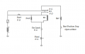
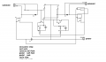
valve is 12vdc solenoids 5 amp max current. one coil forward, one coil reverse.

I want to push a switch and have the system cycle full ahead to limit switch then reverse and stop at another limit switch at home position
I would also llike to have a safety switch in the circuit. eg panic button that when pushed would stop and reverse the curcut, I guess just wired in parallel with the limit switch at full extension would do .

Relays or solid state(transistor) either way works for me. The whole circuit is fed 12v DC and controlling 12v dc.
 

Thread Starter

charlottetown999

Joined Oct 17, 2017
10
I've done a lot more industrial stuff. eg motor contactors, control systems for boilers old school analog stuff relays mechanical switches etc.
Its a rather simple circuit, was just hoping someone had a text book or something already on hand they would post up on here

Yes the entire point of the thing is to have the thing turn fluid power on to the piston end of cylinder, go till it hits limit switch reverse then stop at home position. Its for a wood splitter machine. I just want to push a trigger button on my control panel and have it go full cycle and stop.

I might have to go see if my buddy still has the exhaust tubing bender as its pretty much what i need to replicate.
 

MaxHeadRoom

Joined Jul 18, 2013
28,617
I am assuming you mean a simple solenoid. i.e. non-servo valve?
If the positioning is to use a simple L.S. then simple relay control can be used.
Typically industrial tube benders use hydraulic servo valves with encoder feed-back.
Max.
 

philba

Joined Aug 17, 2017
959
Yes, a couple of relays and limit switches should work. Though getting the limit switches set up wrong has the potential of destroying your machine. I have no idea on selection of the components - they'll need to be able handle the currents and forces involved. I'd be pretty careful selecting the right relays. I'd be worried about the time it takes to stop the forward motion and start the reverse - you might destroy the limit switch before reverse can start. One other question I have - 12V, 5A is only 60 Watts, is that really going to be enough force to split wood? I've hoisted a splitting maul more times than I can count and that feels like it's a LOT more than 60 Watts of power. Aren't most splitters hydraulic?

This should do it electrically. One thing I'm unsure of is the effect of the collapsing magnetic field in the forward solenoid. It could spike the relay coil. You might want to use a DPDT relay to switch the solenoids instead of the SPDT that I have drawn.
[edit] Don't hold the start button down while it's running[/edit]
reversing relay.png
 
Last edited:

strantor

Joined Oct 3, 2010
6,782
The single relay approach is simpler. Though the panic switch should be in line with the power as you might need to stop the reverse stroke, too.
I had no idea what you were talking about "single relay." Read it a few times and gave up. Then I spent more time looking at what #12 posted. I thought there were 3 relays there when I saw it the first time.

Yeah so I agree, what #12 posted is probably the simplest way possible to make this circuit (and I applaud that) but with not stop in reverse it could be a safety issue.

Edit: the panic switch could be moved to the left right after the fuse.

Edit 2: but if you moved the panic switch to the left like that, reverse movement would begin automatically again upon releasing the switch. Still a safety issue.
 

Thread Starter

charlottetown999

Joined Oct 17, 2017
10
Just getting back to this.

The bender I repaired years ago was a Blue Boy, similar to a HUTH or the import ones sold by Baileigh. Much simpler than the one in the vidoe above. Just a standard muffler shop bender with automatic angle stop.

The hydraulic circuit has a pressure relief valve set well below the safety rating of all the components.
I will likely have both a physical cycle limit switch wired in parallel with a pressure sense switch in the hydraulic line

I think they had used C106D transistors in place of relays with some assorted caps and resistors to control voltage spikes. it also had a bridge rectifier section as input was AC from a transformer that also fed the pump drive motor but thats a bit irrelevant here

Also they had a set of forward and a reverse jog switches which I don't require.

I will try and find my notes from the project. I'm sure I kept them in a scribbler somewhere.
 

Thread Starter

charlottetown999

Joined Oct 17, 2017
10
This is what notes I found in my scrapbook. there was possibly a connection from sw2 NO pole to sw8 lower contact NO pole, and where would the other pole of the power supply attach to?

Transistors were C106D, I might need a little higher amp rating
I think they were replaced with NTE 5457 when I repaired it

As for transistor over relay, 50 cent part vs $20 ish for relay and socket. that would be the motivation.
 

Attachments

philba

Joined Aug 17, 2017
959
Wow, that makes my overly complex approach look simple. 8 switches. It's definitely doable with transistors though it needs to be designed from an "automotive engineering" perspective. Things like nasty transients and such. The fact that you had to replace the transistors says that the pipe bender circuit wasn't fully protected. The relay approach would be pretty rugged, not sure of a transistor version.
 

Thread Starter

charlottetown999

Joined Oct 17, 2017
10
Its not your average wood splitter. Ram is 4" dia bore is 5" travel is 33" cycle time shold be around 7 seconds full out full return under load.

Valve is D08 size pilot operated so I'm basically controlling a D03 valve that sits on top of the larger valve. Oil flow on the piston end for return stroke is about 80gpm. I'm still thinking a secondary diverter valve will be needed on it.

There's actually 2 of these controld on the machine. Another will run a d05 valve that feeds a sequence valve for log clamp and saw head.

For an idea of the whole machine look up bells or rapido loco firewood processor on youtube

It basically me being cheap. Figure I can make these 2 boards and house them in an ammo box for $50. Factory units I've been quoted $200 up... each...
 

Thread Starter

charlottetown999

Joined Oct 17, 2017
10
Wow, that makes my overly complex approach look simple. 8 switches. It's definitely doable with transistors though it needs to be designed from an "automotive engineering" perspective. Things like nasty transients and such. The fact that you had to replace the transistors says that the pipe bender circuit wasn't fully protected. The relay approach would be pretty rugged, not sure of a transistor version.
 
Top