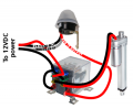
Automatic chicken door is becoming my guillotine

Thread Starter

Sofa

Joined Dec 24, 2020
250
When the relay is disconnected the actuator must move back in.
Without the relay the actuator pin won't move back in, there is no power! If I shut off the transformer the click is there and it tells me the next step will be the power will flow the other way but there isn't any as I turned the transformer off.
 

Thread Starter

Sofa

Joined Dec 24, 2020
250
I normally read fiction.
This could be a best seller!
I like the bit about your bike.
Good luck, you are getting there.
Thank you sir!

I may get there, one day, somehow, thanks to these incredible people.

And keep in mind that some of us study for years and years just to understand one part of our body. Complete abracadabra to most. Just like 'electronics' is abacadabra for most folks. That too is a specialization.
 

Thread Starter

Sofa

Joined Dec 24, 2020
250
And when do you plan to wire it permanently? The relay part at least, now that you know it's working.
When I can find a better quality 12V light sensor. The diagram is simple, connect a few wires and it works! Well, it SHOULD work. I suppose that if I had a proper photo cell right now it would be a piss.
 

Thread Starter

Sofa

Joined Dec 24, 2020
250
What do you mean by "without the relay", relay goes where? Why is there no power? Why do you shut off the transformer?
Ok, let me try to explain in English and according to my knowledge! Normally there is always power flowing one way. The bulb lits up. Or the actuator pin moves out. So how does it move back in? By making sure the power flows in the opposite way. And that the relay's job.

Now, I connect the relay to the actuator and the transformer. BZZZZZZZZZ goes the thing and moves out. It stops at the end.

Job done.

How do I get it to move back in? Not by just sitting there. So, and now comes the assumption, the power normally comes from the transformer, goes through the photo cell then towards the relay. The relay also gets power directly. The moment the photo cell says its bed time or wake up time the power goes on or off and because of the change the second circuit in the relay is activated and the power flows the other way so the actuator retracts.

Without a proper functioning photo cell I cannot simulate that.
 

Thread Starter

Sofa

Joined Dec 24, 2020
250
Guys, let me start all over again, by myself. I have frustrated you enough and taken up far too much of your time. I am going to read it all again, back to page 1 and I will try to find a couple of hours in peace so I can concentrate. There are so many pages now with information and it's time to bring down the 100.000 words to a few sentences that are clear. It can't be that complicated and now it is and that is my fault.
 

LesJones

Joined Jan 8, 2017
4,521
If you have now decided to give up on solving the sensor problem then you can simulate it with a switch using the diagram in post #175. Your drawings of the relay pinout and the socket pinout are correct so you can wire it up using the relay socket.
If at some point in the future you want to go back to solving the sensor problem then find a way to remove the circuit board from the base so you can take a picture showing all of the etch side of the board. We can then trace out the full circuit so we understand how it was designed to work. My feeling is that they were originally built to work with 230 volts AC and someone (Other than the designers.) has tried to modify them to work on 12 volts DC.

Les.
 

Thread Starter

Sofa

Joined Dec 24, 2020
250
No, I never give up. I am way too stubborn for that. I just don't want people to read this posting as a source of amusement. If so, that itself is fine but it also means I am wasting too many good people's time so I decided to start again, by myself. And when I have something positive to tell I will place a new message.

MrChips. That could be an option but it would be better if I got a 12V cell that works as a 12V cell. It doesn't have to last for years, it just has to work. If in time it decides to pack up on me I'd just pop in another one. Things do break down, even good things. So that's not the issue. If I don't wake up in the morning I want my wife or daughter to be able to fix it. Like sticking a new relay in the holder. Anyone can do that. But thank you too for the offer!
 

Thread Starter

Sofa

Joined Dec 24, 2020
250
If you have now decided to give up on solving the sensor problem then you can simulate it with a switch using the diagram in post #175. Your drawings of the relay pinout and the socket pinout are correct so you can wire it up using the relay socket.
If at some point in the future you want to go back to solving the sensor problem then find a way to remove the circuit board from the base so you can take a picture showing all of the etch side of the board. We can then trace out the full circuit so we understand how it was designed to work. My feeling is that they were originally built to work with 230 volts AC and someone (Other than the designers.) has tried to modify them to work on 12 volts DC.

Les.
I can try the switch, that's easy enough. Thank you too.
 

MrChips

Joined Oct 2, 2009
35,017
No, I never give up. I am way too stubborn for that. I just don't want people to read this posting as a source of amusement. If so, that itself is fine but it also means I am wasting too many good people's time so I decided to start again, by myself. And when I have something positive to tell I will place a new message.

MrChips. That could be an option but it would be better if I got a 12V cell that works as a 12V cell. It doesn't have to last for years, it just has to work. If in time it decides to pack up on me I'd just pop in another one. Things do break down, even good things. So that's not the issue. If I don't wake up in the morning I want my wife or daughter to be able to fix it. Like sticking a new relay in the holder. Anyone can do that. But thank you too for the offer!
The sensor looks straight forward enough. For me I would have liked to know what the circuit looks like and why it does not work.
(You are not wasting anyone's time. This is what we do on AAC for entertainment.)
 

Thread Starter

Sofa

Joined Dec 24, 2020
250
Insight. Understanding. Experience.

In a day or 2, when I get the balls to connect in my brain, I will get to a level that should be sufficient to build a device from the locker lights, the media players, the electric drill and the actuator that should be able to reach the moon and remove the Chinese flag.
 

Thread Starter

Sofa

Joined Dec 24, 2020
250
Eeeeeeeeh, could it be that the internal pin connections of the 8 pin relay I have got DIFFER from the one in the diagram of the American guy who showed where all the wires go? Or are all 8 pin relays internally equal, apart from the quality?
 

Thread Starter

Sofa

Joined Dec 24, 2020
250
Because I am trying to get the relay to work. It normally has a constant power and one that goes on and off, in my case from the photo cell. Instead of the photo cell red wire it's double connected to the transformer. When the pretended photo cell red wire is removed the circuit should run the other way round. It clicks alright and the contacts of the relay move just fine but once the actuator is out, or in, it won't go the other way. That simply means there is no power though the relay itself is under power. That's why I was wondering if all relays are the same inside. Sounds logical to me.
 

djsfantasi

Joined Apr 11, 2010
9,237
Eeeeeeeeh, could it be that the internal pin connections of the 8 pin relay I have got DIFFER from the one in the diagram of the American guy who showed where all the wires go? Or are all 8 pin relays internally equal, apart from the quality?
Very likely. You can use your multimeter to find out. Two pins will show a resistance between them and no connection to any other pin. This is the coil. Two pairs of pins will show 0 resistance. Each pair is a set of normally closed contacts. Use a power supply or battery and activate the relay. The two pairs of contacts will no longer be connected. And one of the pins will show 0 resistance to one of the pins that weren’t connected to anything. This pin is the contact common. The geometry of the contacts should provide hints as to which is what.

Difficult to describe. But try it. It’s just a DPDT switch activated by the coil.
 

Thread Starter

Sofa

Joined Dec 24, 2020
250
Very likely. You can use your multimeter to find out. Two pins will show a resistance between them and no connection to any other pin. This is the coil. Two pairs of pins will show 0 resistance. Each pair is a set of normally closed contacts. Use a power supply or battery and activate the relay. The two pairs of contacts will no longer be connected. And one of the pins will show 0 resistance to one of the pins that weren’t connected to anything. This pin is the contact common. The geometry of the contacts should provide hints as to which is what.

Difficult to describe. But try it. It’s just a DPDT switch activated by the coil.
My multi meter consist of 10 fingers and a strong heart.
But if the internal contacts of my relay are NOT the same as in the relay from the American it would explain a lot.
And here we go again, for 59 years I have been able to survive without a multi meter so that's definitely not something I want to throw my money at. The only option is ........junk!
 

Thread Starter

Sofa

Joined Dec 24, 2020
250
One thing I noticed (just now) is that the vertical pins in this picture are at the bottom whilst the wires hardly visible at the top look like mine but the vertical pins of my relay are at the top

wiring.png
 
Top