Auto-switchover for E-Bike controller

Thread Starter

deepak4you

Joined May 1, 2010
51
Hello to all experts,

I need help in a circuit design that I'm trying to build.

What I have:
1. 1000W E-bike controller with throttle
2. 48V battery
3. Boost converter (currently set to 54V)

How things work:
When battery is connected to controller and throttle is engaged, the controller draws power from the battery and powers the motor
When I don't engage the throttle and the vehicle is still moving, there's "regenerative" voltage at the same terminals of the controller that are connected to the battery. This regenerative voltages varies with speed.

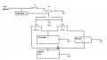
What I wish to achieve:
1. When I engage the throttle, power should be drawn from the battery and supplied to the controller
2. When I don't engage the throttle and the vehicle is still moving, the output of the controller should get connected to the input of the booster. Output of the booster connects to the battery so that battery can be charged

To achieve this, I've designed the attached circuit. Although I'm an electronics graduate, my experience in electronics/power electronics is limited and hence this query.

My specific queries:
1. Is this circuit crudely workable?
2. If yes, then is the MOSFET configuration correct? I'm concerned about the Drain and Source terminals being correctly connected in the circuit
3. Any other modifications that might help?

Thanks a ton in advance.
P.S: My apologies for making a crude circuit in powerpoint
 

Attachments

wayneh

Joined Sep 9, 2010
17,498
To achieve this, I've designed the attached circuit.
I'm a little unsure why. It sounds like the existing setup does what you want. You appear to only be adding the voltage boost. Is that so, and why are you adding it?

Where is your gate voltage coming from? And maybe you can walk us through the logic of what you're trying to do with those MOSFETs.
 

Thread Starter

deepak4you

Joined May 1, 2010
51
I'm a little unsure why. It sounds like the existing setup does what you want. You appear to only be adding the voltage boost. Is that so, and why are you adding it?

Where is your gate voltage coming from? And maybe you can walk us through the logic of what you're trying to do with those MOSFETs.
Yes indeed the controller is giving me regenerative voltage when not drawing current from the battery, but:
1. The regenerative voltage is varying with speed and not constant
2. Having, say, 15v regenerative voltage from the controller doesn't help charging a 48v battery. Hence i am using a boost converter that gives me constant voltage of about 54v to charge my battery
3. Right now I'm using a very forgiving VRLA battery pack so variable voltage might be ok. But i plan to add a lithium pack soon for which a variable voltage and ad-hoc/stop-go charging wont work. Hence building a setup where the charging voltage remains constant
4. I'm using MOSFETs because the current in the setup. Battery-controller drain is about 21A max hence i'm using IRF4110 there and my boost converter has a rating of approx 12A hence using IRFZ44 on that path.
 
Last edited:

Thread Starter

deepak4you

Joined May 1, 2010
51
5. I'm actually using this setup to build a hybrid scooter. So the gate voltage is coming from the ignition of scooter. I added a small 18v boost circuit to raise the voltage from 12v to 18v to esure that the MOSFETS get all the gate voltage they need to turn fully ON. I cant afford losses from 48v battery to the motor.
 

Thread Starter

deepak4you

Joined May 1, 2010
51
Looking at the datasheet of 4110 and Z44, I think 12V coming from ignition should be enough to drive the gate. Probably 18v boost is not needed.
 

qrb14143

Joined Mar 6, 2017
112
Where does the motor fit into this diagram? Also, I'm a bit unsure as to the relay at the top of the diagram, it would appear that it's purpose is to apply 18V to one of the gates but a relay would seem massively over the top to switch a very small gate current.

I would have thought that a better solution would be to have all your "control" circuitry done at low voltage ie 3.3V or 5V then use a gate drive IC to drive your MOSFETs.
 

Thread Starter

deepak4you

Joined May 1, 2010
51
Sorry I don't have the ppt file with me right now, so I'll put a text update till then:

1. Motor is a 3 Phase motor driven by the output of the controller which is not shown in the diagram currently.
2. I'll use a reed relay connected in series with the ignition/18V boost board to turn the relay on/off
3. This reed switch itself will be energised based on position of the throttle (which is a crude threshold of speed of the vehicle). At a particular position of the throttle, reed switch will be energised --> Relay turned on --> N/O contact is closed
4. N/O and N/C Relay contacts will be connected as follows:
N/O: for closing the left side MOSFET
N/C: for closing the right side MOSFET (Boost circuit side)
5. With the help of the relay, i can ensure that only one MOSFET is on at any given time. The relatively longer switching time of the relay contacts helps me ensure that the MOSFETs also have enough time to switch ON/OFF. I know MOSFETS have really fast switching times, but I'm being over-conservative here. Having both MOSFETs ON even for a moment might turn out to be quite explosive ;) Also, implementing a relay is just a little bit easy for me right now.

With all this, what I'm trying to achieve is:
1. At low speeds + ignition ON, Reed switch is ON and left side MOSFET is on and battery supplies current to the controller/motor
2. After a certain threshold speed + ignition ON, Reed switch is OFF and right side MOSFET is on with controller supplying regenerative voltage for charging the battery
3. At 0 speed + ignition ON, although the Left side MOSFET is on, there's no regenerative voltage towards the battery. The diode prevents current from battery to reverse feed the Boost module
4. At 0 speed + ignition OFF, everything is OFF

This is a patented design of mine and I'm trying to build prototype for the same.

I'll upload a more descriptive diagram little later.
 

ScottWang

Joined Aug 23, 2012
7,400
Thanks Scott. I'll make the changes as highlighted. That was one of my queries to see if the D & S lines are correct or not. Both side positive poles had me confused.
Your original circuit will make the current flows through the diode not DS and connected two Vg together will make the Relay lost its function.
 

ScottWang

Joined Aug 23, 2012
7,400
If you don't want to get the 12V from ignition of scooter, probably you can get it from 48V which in series with a 30V/1W zener and connects to a 78M12, so you have +12V to provides for 12V relay and the Vg of MOSFETs.

A best voltage range of voltage is 48~51V for a 48V battery, and keep the charging voltage above 56V.
48V-Battery-Maintenance.
 

Thread Starter

deepak4you

Joined May 1, 2010
51
If you don't want to get the 12V from ignition of scooter, probably you can get it from 48V which in series with a 30V/1W zener and connects to a 78M12, so you have +12V to provides for 12V relay and the Vg of MOSFETs.

A best voltage range of voltage is 48~51V for a 48V battery, and keep the charging voltage above 56V.
48V-Battery-Maintenance.
I actually want the gate signal to be actuated from the ignition so that the whole vehicle - ICE and Battery Motor - both are Enabled/Disabled or On/Off with the ignition.

The thing with the 30V zener is great. I was at one point stuck with getting 12V out of 48V and was thinking of ways to achieve it but couldn't. Although I don't think I'll need it now, but I know what to do when I do!

Attached is the updated circuit diagram. Any other improvements I should consider?

E-Bike Setup_v1.1.jpg
 

Thread Starter

deepak4you

Joined May 1, 2010
51
Got it Scott. I made the ckt in ppt, so couldn't flip the MOSFET. I'll build the ckt, test and update. Thanks a ton for your help. You guys rock!
 

Thread Starter

deepak4you

Joined May 1, 2010
51
I built this circuit, but for some reason, the switching is not working. Neither of the two swtiches seem to be turning ON. Individually, the MOSFETs seem to work but not in the above configuration. Is it possible for someone to help simulate this circuit and check if this would work? Unfortunately I'm too much of a newbie and don't have any simulation tools, hence the cry for help.

Thanks a ton in advance.
Deepak
 

Thread Starter

deepak4you

Joined May 1, 2010
51
Getting back to this thread after a long time. Apologies for that. I was busy building the other aspects of the prototype.

So I testing this above ckt by testing the MOSFET switching individually on the same board with an LED load. What happens is that once the MOSFET/LED turns ON after supplying gate voltage, it stays turned on. This is happening with both MOSFETs. I see that the LED is dimming very slowly implying that the voltage at the gate seems to be held up by a capacitor. Probably the internal capacitance combined with the gate pull down resistor? I'm currently using a 13k pull-down resistor on the gate. I could use a 1k resistor, but if the gate capacitance is what is holding up the charge and leaving the MOSFET ON for longer is indeed the reason, then a 1k resistor would still leave the MOSFET ON for lot longer. I need an immediate switch (couple hundred microseconds) of the MOSFETs.

Any thoughts?
 
Last edited:

Thread Starter

deepak4you

Joined May 1, 2010
51
I forgot to mention that without connecting the D and S of the two MOSFETs together, when I then test the ckt individually, it works perfectly fine. The extended ON time of the MOSFETs is seen only when the ckt is operating with the common D and S connected.
 
Top