Facebook
 Google
 GitHub
 Linkedin
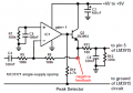
Hi there, I am creating an audio headset tester and need to add a vu meter to display the amplitude of the output waveform, the signals amplitude can get changed with a potentiometer earlier in the circuit. I have it set up so far that the audio signal goes into a diode and capacitor to push it into the positive range and then into a peak detector that will be displayed on the vu meter, I am using a LM3914 to drive a bargraph, the signal input to pin 5 is 5v max so I have a voltage divider to get the output from the detector to 5v max, the problem is that since it is a resistor and capacitor it is creating a filter that it altering my audio signal output. To try fix this I have a op amp acting as a buffer and then the divider after. I am wondering if there is a easier way to do this, also proteus seems to bug quite a bit as when I change the potentiometer the bargraph doesn't change until I restart the simulation.