Audio amplifier and transformer step up voltage

Thread Starter

Leo Silver

Joined Apr 27, 2016
46
Hi all,

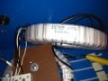
I tried to step up a voltage from a signal taken by the output of a MOSFET amplifier. The amplifier works fine steppping up my signal which comes from a function generator (a typical 10Vpp 20kHz sinusoidal). The problem arises when I try to step this signal further up using a transformer. I have three identical transformers that are supposed to be about 1:400. One of them just gives me a voltage which is similar to the input with a slight phase shift and lower peak value. I thought that this one might be short-circuited inside (although I am not sure about the phase shift then) so I tried to use one of the other two but they seem to step down my voltage 3 times. I paid attention to apply the signal at the primary. There are 6 cables for the primary and two for the secondary with thicker insulation so I believe this is my secondary winding's output. The primary's 6 inputs consist of 3 white and 3 black cables thus I believe there are 3 different coils in the transformer. I connected them in parallel meaning all the white cables together and all the black cables together but it doesn't seem to work this way. I am not sure if this is a problem of the transformer or if I do something wrong here.. If someone could provide some advice that would be really helpful!
 

MrChips

Joined Oct 2, 2009
30,806
What is the make and model number of the transformer? Show us a photo or link.
Is the transformer a power transformer or an audio transformer?
 

AnalogKid

Joined Aug 1, 2013
11,042
1:400 is a huge turns ratio for a signal transformer; are you sure about the numbers?
No part numbers, no photos, no schematic ... no answer.

ak
 

Bordodynov

Joined May 20, 2015
3,179
Probably the reason for the small inductance. When working at a fixed frequency, it is possible to adjust the resonance with an additional capacitance. And maybe the transformer has a large capacity. In this case, you need to select the frequency of the signal. Another way is to include the transformer in the feedback. In this case, the resulting generator will itself operate at resonance.
 

Thread Starter

Leo Silver

Joined Apr 27, 2016
46
1:400 is a huge turns ratio for a signal transformer; are you sure about the numbers?
No part numbers, no photos, no schematic ... no answer.

ak
You are right I made a mistake it is 1:45. The transformer is an ANTRIM transformer 7438X although I couldn't find something on the manufacturer's site. One of the three I have has a label saying 0-75V primary to 0-3.5kV secondary. That's all the info I have. The frequency I was operating is 20-40kHz. The output of the transformer was monitorred with a high voltage probe without any load connected.
 

dendad

Joined Feb 20, 2016
4,476
Is it an iron core transformer, like a power transformer?
It is most likely you are trying to run way beyond the transformer frequency range.
have you tried starting at 60hZ and see how it works?

Have you measured the windings with a ohm meter?
Can you put up a picture?
 

Thread Starter

Leo Silver

Joined Apr 27, 2016
46
Hi thanks for the reply! It is an air cored transformer! It definitely doesn't saturate as the output is a perfect sinusoid. I only tried the range of frequencies that I described earlier..
 

MrChips

Joined Oct 2, 2009
30,806
Getting there.
That is not an air cored transformer. It is likely to have a ferrite core.
You need to know the frequency range and its intended application. If it is a power transformer then it is no good for wide-band audio application.
 

Thread Starter

Leo Silver

Joined Apr 27, 2016
46
Most likely you are right but how did you manage to see that it is a ferrite core transformer? Is it a typical thing for toroidal transformers like this one?
 
Last edited:

MrChips

Joined Oct 2, 2009
30,806
How did you manage to see that it is a ferrite core transformer?
I didn't. All I can see is the photo you posted.
I see enameled copper wire wrapped around a circular core with a square cross-section wrapped in white plastic. This is known as a toroid.
For a transformer to work efficiently it has to have a ferro-magnetic core. The most common types of transformer core construction are iron laminates or ferrite material.

Here is what E-I laminated core would look like:


Here is what a bare ferrite core would look like:
 

crutschow

Joined Mar 14, 2008
34,428
For that frequency range you could use a tube (valve) audio output transformer and operate it in reverse, by feeding the signal to the speaker output leads and taking the output from the plate leads.
 

dendad

Joined Feb 20, 2016
4,476
It looks like a toroidal power transformer to me and that will be most likely iron core made from a wound tape.
Run your system at 50 or 60Hz as I asked earlier and see if it works at those frequencies.
The transformer is the problem I suspect. And those are just not suitable for your application.
 

dendad

Joined Feb 20, 2016
4,476
And I just had a thought...
Some years ago I was involved in designing and installing a propeller bearing temperature monitoring system on a navy ship. It had odd power supplies. You could also try at 400hZ if my memory is correct.
Running up a range of frequencies to find the self resonant spot could be interesting too. A couple of turns around the transformer core and fed to the amp inputs and you have an oscillator. Then it will pick the frequency it wants to run at.
If it does not oscillate, swap the wires over.
 
Last edited:
Top