I think the circuit will work only if the transistor used has a high hFE so that it is saturated with no signal. When there is an AM radio station received then when loud the negative excursions of the high amplitude radio waves reduces the base bias which causes the collector to use less current in the 10k resistor producing a positive output swing.
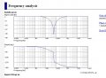
Crystal radios were used a long time ago when there was only one or two radio stations around you. Not much interference.Today it would pickup maybe 10 or 20 AM radio stations at the same time because it has only a single LC tuned circuit. A real AM radio has six or more LC tuned circuits so that it rejects interference from other station frequencies.
Made this, it works!! (copper clad)..think understand a little on it now..made transistor amplifier for it
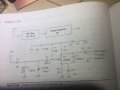
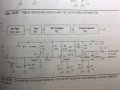
C3 is not needed it seems..what's not needed? R7 variable 1k and C2 variable
Same as the books' but added Q3 and Q4, Q4 to amplify the signal more before sending it into the distortion transistor...since Q4 then no need for Q2?
Also, don't really understand how the power detector works (but it has to distort the signal : clip at some point ) : this is mixer? or unmixer?
..it clips the signal but the RF signal is still available..Normal crystal radio with diode has capacitor later to extract the audio (correct?)..what is extracting the audio in this case? what is c10 for?
Also, any way to "test" on spice? what to test?
Thanks
I have a “Red Sox Radio” I built to pick up only a single station, the one that broadcasts Red Sox games, AM 1440. It has one tuned circuit made by the ferrite rod antenna plus a fixed capacitor and trimmer to fine adjust the tuning. The tank circuit is input to an MK414 AM radio chip, which has an untuned RF amp, AGC and detector. It works fine, discriminating the channel quite well in in area with plenty if AM stations.
watching the signal on scope from antenna, there is 60hz signal (noise)...what causes it? and can use diff amp to remove it?? : can't attach image unfortunately
 Facebook
 Google
 GitHub
 Linkedin

 need to get back to study