Attempting to make an AM receiver for uni

Thread Starter

obcoop

Joined Aug 29, 2026
2
1788018249278.png

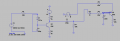
Am new to LT Spice and circuit design, however I have a solid grasp of the basics (I think), I've been trying to use ai chatbots to help with debugging but they just confuse me more! What is wrong here? I am trying to create an AM receiver for 900KHz, currently using both transient simulations and AC sweeps to view results and the above circuit design doesn't do anywhere near as intended. I know there's likely alot wrong so where do I start?
 

MrChips

Joined Oct 2, 2009
35,137
Before you start building real circuits, you need to compile and understand the inner workings of the building blocks required to meet your objectives.

  1. Tuned RF circuit
  2. RF amplifier
  3. AF amplifier
  4. Demodulator

As pointed out, you need to learn how a BJT amplifier works and how to bias the transistor properly.
 

ci139

Joined Jul 11, 2016
2,031
at past . . . we used stick ferrite coil 360pF adjustable trim cap. and a diode rectified to 300 ... 600 Ω dynamic speaker to bearly hear a nearby (few/single km away) with long enough air wire and earth ground ←← this without any batteries/power-supply

i guess the net is full of 1960-s 70's circuits for such - easy to modify for distant station receiver using RF and output power amps . . .

?? https://awsh.org/simple-am-regenerative-receiver/ . . . !! -- altough the 2n34 is a leaky Ge - it'd best to DC bias/ground at capacitor side (i assume)
 
Last edited:

du00000001

Joined Nov 10, 2020
200
at past . . . we used stick ferrite coil 360pF adjustable trim cap. and a diode rectified to 300 ... 600 Ω dynamic speaker to bearly hear a nearby (few/single km away) with long enough air wire and earth ground ←← this without any batteries/power-supply

i guess the net is full of 1960-s 70's circuits for such - easy to modify for distant station receiver using RF and output power amps . . .

?? https://awsh.org/simple-am-regenerative-receiver/ . . . !! -- altough the 2n34 is a leaky Ge - it'd best to DC bias/ground at capacitor side (i assume)
I'd replace some old Ge diode by some shiny "new" Schottky diode. Might be just as leaky but has somewhat similar forward voltage. And for the last 40 years or so I`d use an LM386 for audio amplification. (OK - the TL081 might be about the same age, but IIRC the LM386 has more output power. . . . Saw now in the text section that the poster also used the LM386 :) - just not in the schematics.)
 

MrAl

Joined Jun 17, 2014
13,790
View attachment 370851

Am new to LT Spice and circuit design, however I have a solid grasp of the basics (I think), I've been trying to use ai chatbots to help with debugging but they just confuse me more! What is wrong here? I am trying to create an AM receiver for 900KHz, currently using both transient simulations and AC sweeps to view results and the above circuit design doesn't do anywhere near as intended. I know there's likely alot wrong so where do I start?
Hi,

Yeah a couple things don't look right.

To start, the L1 and C1 tank look like they are in series at first glance because of the inadvertently deceptive way they are drawn, but in reality they are in parallel. That means that Q3 gets almost no current at resonance. Since resonance is around 1MHz that means around 1MHz you get no signal through to the output. That's opposite to what you really want. With L1 and C1 in series, you get maximum current through to the output, which is what you really want.
Check it out and see what happens when you place L1 and C1 in series.

Without leaving the L1, C1 situation just yet, your choice of L1 could be making the response too sharp too, which would make tuning very hard or maybe impossible, and if you do get it right you may not hear much of the program audio because the signal bandwidth could be far too narrow. You should check into that. In the US the bandwidth for an AM radio signal is 20kHz which centers on the center frequency.

As someone already said, Q3 looks like it is biased incorrectly so check into that also. Q2 also does not look correctly biased, it needs some DC bias to work right, and I don't think you can depend on the collector base leakage current for that bias.
 

MrAl

Joined Jun 17, 2014
13,790
Hello again,

It is also a little interesting that the bandwidth is:
BW=R/(2*pi*L) {in Hertz}

where R is the loading resistor. It's interesting because it does not include the capacitor value nor the center frequency.
R here would be the input resistance of the circuit with L and C in series with that input resistance (such as the input to a transistor base at these frequencies or lower).
It is usually ok to divide the bandwidth by 2 in order to get the bandwidth on each side of the center frequency.
 

MrAl

Joined Jun 17, 2014
13,790
? R.load is R.ser<.V1 + .GND.loop + .L1 + .rB.Q3> + hFE.Q3 × (R.ser.rE.Q3 + R3) ← simplified for a ⚠low frequency

https://share.google/aimode/os44TWiByMJLwXBBJ ← an Ai "sanity check" according to which the : \( BW=\frac{f_0}Q=\frac{f_0R_{TOT}}{X_L} \)
Hi,

I think if you are going to post equations and equivalent solutions to something you should make the post more clear by using more common notations.
Yes, BW is also related to Q but part of your expression is not that easily read because some of the variables are not defined. I never like to guess because it leads to misunderstandings.

Pure text is perfectly fine too, and allows others to copy and paste into math software more easily.

R=2*pi+N
Vout=Vin*A+V2

That's simple enough to understand as long as we know what R is, N is, A is, and V2 is, and maybe a schematic which is always a good idea.
 
Top