Facebook
 Google
 GitHub
 Linkedin
Ok, I am having trouble getting my program on the chip.
The code compiles fine. But I still am a little lost on how to hookup the programmer to the chip.
I get a red light on the programmer which probably means I didn't set the pin connections correctly.
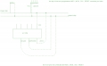
I have the programmer ATAVRISP MKII it has a 6 pin connector
which when I look up the pin out in the data sheet it has
MISO , MOSI , GROUND , RESET ,SCK , VCC
I know pin one is where the triangle symbol iis on the connector.
Then All I did is plugged connectors MISO to chips MISO ,...etc etc
SO it is one to one corospondence.
But I am confused about how to rig the VCC and ground because their are 2 ground pins on the chip and their are 2 power pins on chip VCC, AVCC
Plus On AVRFreak they told me I need a battery with the programmer.
But I thought the programmer programs the chip with the power from the usb port. Didn't think you need a battery to program the chip.
Either way I am looking thru the data sheet for ATmega32 and I can't find
What voltages the the chip uses, and what the output voltage oin a pin would be. I need this info so when I do succeed in programming the chip.
I don't destroy it.
This is very frustrating because I have everything programmed and ready .
But I cann't get it on the chip. The datasheet is kind of help full but I cann't find the info I need. I know it's some where in the 346 pages...AAAAAAAAAAAAAAAAAHHHHHH
I am currently using programmer connector to the chips 6 - 11 pins.
But I may need to connect it with pins 30 , 31 ? I am shaky on this .
I have just read on the first page in tiny bold letters Atmega32 uses 4.5 to 5.5V. Would it be ok to use 3 1.5 volt alkalane batteries in series? Or is their a specific battery you can buy for the chip.
Thanks for any help.
I wish I could get this programmer to program the chip I am anxious to get the chip running.
I am using AVR studio version 4 with WinAvr gcc C programing instead of ASM programming for my IDE.
The code compiles fine. But I still am a little lost on how to hookup the programmer to the chip.
I get a red light on the programmer which probably means I didn't set the pin connections correctly.
I have the programmer ATAVRISP MKII it has a 6 pin connector
which when I look up the pin out in the data sheet it has
MISO , MOSI , GROUND , RESET ,SCK , VCC
I know pin one is where the triangle symbol iis on the connector.
Then All I did is plugged connectors MISO to chips MISO ,...etc etc
SO it is one to one corospondence.
But I am confused about how to rig the VCC and ground because their are 2 ground pins on the chip and their are 2 power pins on chip VCC, AVCC
Plus On AVRFreak they told me I need a battery with the programmer.
But I thought the programmer programs the chip with the power from the usb port. Didn't think you need a battery to program the chip.
Either way I am looking thru the data sheet for ATmega32 and I can't find
What voltages the the chip uses, and what the output voltage oin a pin would be. I need this info so when I do succeed in programming the chip.
I don't destroy it.
This is very frustrating because I have everything programmed and ready .
But I cann't get it on the chip. The datasheet is kind of help full but I cann't find the info I need. I know it's some where in the 346 pages...AAAAAAAAAAAAAAAAAHHHHHH
I am currently using programmer connector to the chips 6 - 11 pins.
But I may need to connect it with pins 30 , 31 ? I am shaky on this .
I have just read on the first page in tiny bold letters Atmega32 uses 4.5 to 5.5V. Would it be ok to use 3 1.5 volt alkalane batteries in series? Or is their a specific battery you can buy for the chip.
Thanks for any help.
I wish I could get this programmer to program the chip I am anxious to get the chip running.
I am using AVR studio version 4 with WinAvr gcc C programing instead of ASM programming for my IDE.
Last edited: