 Facebook
 Google
 GitHub
 Linkedin
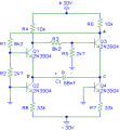
Hi, I'm trying to analyze this circuit

As you can see the base of Q2 and Q4 is at ground and the emiters looks to be at higher voltage than base, so it looks like Q2 and Q4 are always in active region, supposing that the current gain is much greater than 1, then base current of Q2 and Q4 is ~0A and (Ic2=Ie2, Ic4=Ie4), so basically Q2 and Q4 are like current sources.

- First I assume that Q1 is on active region and Q3 is off so:

I with this inequality, I find the capacitor voltage for which Q3 turns on

When the capacitor voltage is larger than 2.7V then Q3 turns on and Q1 turns off
I do not know how to find the capacitor load voltage and the tau=RC of the capacitor, what should I do? find the thevenin circuit over the capacitor?
As you can see the base of Q2 and Q4 is at ground and the emiters looks to be at higher voltage than base, so it looks like Q2 and Q4 are always in active region, supposing that the current gain is much greater than 1, then base current of Q2 and Q4 is ~0A and (Ic2=Ie2, Ic4=Ie4), so basically Q2 and Q4 are like current sources.
- First I assume that Q1 is on active region and Q3 is off so:
I with this inequality, I find the capacitor voltage for which Q3 turns on
When the capacitor voltage is larger than 2.7V then Q3 turns on and Q1 turns off
I do not know how to find the capacitor load voltage and the tau=RC of the capacitor, what should I do? find the thevenin circuit over the capacitor?
Attachments
-
 30.2 KB Views: 38
 -
 1.6 KB Views: 37
 -
 6.8 KB Views: 36
 -
 2 KB Views: 36
 roject


