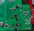
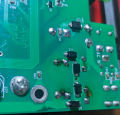
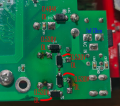
Are these components in the circuit coils or what?

Yeah, what is the reason all 5 caps are dead? Overvoltage?

I have soldered the new ones and will try it out soon.
We have not been told, other than they
Yeah, what is the reason all 5 caps are dead? Overvoltage?

I have soldered the new ones and will try it out soon.
From post #1 " I unsoldered 5 caps at the input, tested them, apparently all broken (good news), ". My guess is that they may have been damaged by over voltage, although there is a statement that "it works, BUT"
 

Thread Starter

rambomhtri

Joined Nov 9, 2015
593
We have not been told, other than they

From post #1 " I unsoldered 5 caps at the input, tested them, apparently all broken (good news), ". My guess is that they may have been damaged by over voltage, although there is a statement that "it works, BUT"
I was asking as in what's your theory this failed. I have not really a good idea about what happened, may be overvoltage...
 

Alec_t

Joined Sep 17, 2013
14,430
How do I check those?
If the resistance measured between any two of its pins is very close to zero then at least one diode is shorted.
If the rectifier is not connected to drive any load and the AC supply is not plugged in to the board, then the resistance between the two pins which connect to the AC supply socket, via those coils, should be close to infinite (overscale reading on an Ohmmeter).
 

Thread Starter

rambomhtri

Joined Nov 9, 2015
593
Yes, it can be. The rectifier circuit steers the DC polarity properly. Think of it as AC at zero Hertz.

Your last image shows +AC by D12. Some new chinese invention. Check all your rectifiers underneath, replace the capacitors, measure if over 8V at pin 1 of the 7805 5V regulator, 5V at its pin 3. Reference ground is pin 2. Its standoff post should be heat-sinked. Come back with observations.
You mean I should measure that ONCE connected to the adapter, with a live board?

I would rather test things disconnected, and then plug the adapter
 

Thread Starter

rambomhtri

Joined Nov 9, 2015
593
Here are some tests I have performed:

1719842021239.png
OL stands for overload

All 5 diodes seem to be working fine!

Any other tests I should perform before plugging in the 9VAC 2A adapter?
I still fear a bit the fact that those 9VAC read with my DMM when there's no load are actually 11.2VAC.

Whatever caused those 5 caps to fail, could have damaged something deeper in the board?
As I said, there is no visual damage at all in the rest of the board, I only noticed the blown caps and knew there was a problem there.
 
Of course, without additional information the best we see is guessing at causes.
I do see what looks like some sort of burn area near diode D9, either due to soldering efforts or a component over heating.
Because of my poor mind-reading ability it is not clear as to the history of the pedal device, leading to a lack of understanding the present issues.
 

Thread Starter

rambomhtri

Joined Nov 9, 2015
593
Of course, without additional information the best we see is guessing at causes.
I do see what looks like some sort of burn area near diode D9, either due to soldering efforts or a component over heating.
Because of my poor mind-reading ability it is not clear as to the history of the pedal device, leading to a lack of understanding the present issues.
Yes, those are the caps on the other side, then ones I replaced. I don't know if that was already there or if I did that with my soldering iron while unsoldering. I put at 340ºC the biggest tip I had to touch both legs so I could pull from the other side the cap. I've done that in the past without any damage, so I don't know why this time I would have damaged anything.

Anyways, should I just plug it in and hope for the best?

Or you want me to test some other things before plugging it in?
 
Top