Are these components in the circuit coils or what?

Thread Starter

rambomhtri

Joined Nov 9, 2015
590
Hello, I am trying to fix my multi-effects guitar pedal Line6 M13 Stompbox Modeler, it does some weird constant noise when I use it, through the amp. I disassembled it and noticed a few capacitors "blown", right at the input of the circuit. By the way, it uses a 9V AC (not DC!) 2A adapter.

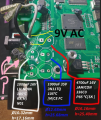
I unsoldered 5 caps at the input, tested them, apparently all broken (good news), and since these are tagged I could find out the specs and replace them. I just soldered them, all fine. Now... before even trying to connect it and turn it on, I would like to know what these 2 components are, the pink ones:
1719661359068.png

I would say they are coils, and the DMM gives me in both about 0.4-0.3 Ohm, so yeah, looks like the short circuit of a coil, but since these are not tagged, I can't replace them and can't know their specs.

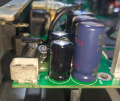
Notice all the damaged caps are at the beginning, and because these 2 components are at the beginning too, I was afraid they would be broken too.

Here are some more pictures before removing the caps:
1719661586039.png

1719661609572.png

Also, parallel to this, the AC adapter is broken too, it's supposed to be a 220V AV to 9V AC 2A (18W), but the reading with my DMM gives 11.2V AC. I opened it and it's just a transformer, no electronic circuit at all. I tested it for shortcircuit and there it was, the output was shorted. I didn't understand then that reading.

I already bought another one, but my question is... what can happen to a transformer (well, in this case it's 100% a short in the output) to give you 11.2V when it was supposed to give 9V?
I haven't thought about it much, but I would say that if you short at some point the secondary coil, the reading would be 0V AC, because 0 Ohm should only give 0V (well, coils are a short but they are generating an EM field inside and I know they don't read 0V). That or AC is messing with me.
 

BobTPH

Joined Jun 5, 2013
9,335
The L16 label visible in the last picture indicates they are indeed inductors.

Why would you want to replace them? The low resistance indicates they are OK.

About the 9V transformer: Unregulated supplies like that will usually show a higher voltage when the load is not connected. I suspect it is also OK.
 

Thread Starter

rambomhtri

Joined Nov 9, 2015
590
The L16 label visible in the last picture indicates they are indeed inductors.

Why would you want to replace them? The low resistance indicates they are OK.

About the 9V transformer: Unregulated supplies like that will usually show a higher voltage when the load is not connected. I suspect it is also OK.
OMG I am retarded!

First... expecting 9VAC and reading 11.2VAC really made me believe something was definitely wrong about it. That's a freaking +25% more voltage, that's a lot more...

Anyways, then checking for a short in the terminals is what confirmed my theory. BUT I AM SO DUMB! Since this was a simple transformer, I am simply measuring the secondary coil, which of course is a short circuit... I think the adapter was OK then... and I bought a new one... my God... to be honest I never faced a +25% error that was fine, and I am not used to shorted terminals in a power delivery adapter, because that just simply sends an image of smoke and sparks to my brain. But then again, it's a transformer, which btw I am not used to check and see "standalone" like that, specially for converting 220V to 9V.

Why changing the coils of the board?
Because they were at the input, next to the 5 dead caps, and just because, they should be cheap and would have bought them to start fresh new. I guess they are fine then... How would you replace those coils if there's no tag?

Don't tell me you have to unsolder them and create yourself a circuit to measure the H?
 

BobTPH

Joined Jun 5, 2013
9,335
There is no reason whatever to replace the coils. They do not degrade or wear out. The only failure would be an open circuit or a short, which could be between windings. The windings appear to be potted in epoxy, so not much chance of a short there. Also, they are likely a custom part, you are unlikely to find a replacement.

Why don’t you describe the problem you are seeing? We have some good diagnosticians here. They will likely do better than guessing.
 

Thread Starter

rambomhtri

Joined Nov 9, 2015
590
The pedal is from a friend, I haven't connected it yet, he told me it turns on and everything works fine apparently, but when you play the guitar through whatever effect, there's a constant loud noise in the background. Still haven't tested it yet as I just replaced the capacitors and have to test it. I'm pretty sure he plugged the 9VAC 2A adapter, originally for 120VAC, to an EU outlet with 220-230VAC, and that broke something (I am guessing the capacitors I just replaced).

Nothing else in the entire board looks fried or broken, just the caps, which were a bit blown, and after measuring them, all broken.

I won't replace the coils, I was just asking how would you find they specs, since they are not tagged.
 

Alec_t

Joined Sep 17, 2013
14,430
If the board uses a 9VAC supply then it must have a rectifier between the board input and those caps. A failed rectifier would allow AC through to the caps, which would cause them to fail.
The rectifier is most likely a bridge rectifier. I see a marking BR1 next to those coils.
 

Externet

Joined Nov 29, 2005
2,252
Those like at L16 location are ferrite core choke coils. If there is no bridge rectifier in the circuitry (BR1), power must be supplied by direct current, not 9VAC or the electrolytic capacitors and much more will fail. My guess is an AC power adapter was used instead and killed the device.
 

Thread Starter

rambomhtri

Joined Nov 9, 2015
590
If the board uses a 9VAC supply then it must have a rectifier between the board input and those caps. A failed rectifier would allow AC through to the caps, which would cause them to fail.
The rectifier is most likely a bridge rectifier. I see a marking BR1 next to those coils.
I did not understand your point... precisely because the input is 9V AC, and not the regular average 9V DC, a rectifier is not needed, which AFAICT is a circuit to transform the AC wave into DC wave. So I don't understand your point at all TBH.
 

Thread Starter

rambomhtri

Joined Nov 9, 2015
590
Those like at L16 location are ferrite core choke coils. If there is no bridge rectifier in the circuitry (BR1), power must be supplied by direct current, not 9VAC or the electrolytic capacitors and much more will fail. My guess is an AC power adapter was used instead and killed the device.
The device indeed has marked as input 9V AC, 2A (18W). This is out of the question. The adapter MUST NOT be DC, which is not typical, but it is what it is. Look at the first picture, it says "AC IN".
 
Last edited:

Thread Starter

rambomhtri

Joined Nov 9, 2015
590
This is the back of the board:

1719676226654.png

The only reason this works with 9VAC is because the rectifier is inside the board instead of the charger?
Why would you do such weird thing?
9VDC is WAAAAY more used and standard, I don't understand, it took me a long time to find a 9V AC charger.
 

Externet

Joined Nov 29, 2005
2,252
Now looking at the bridge circuit underneath, the 'intended for' 9VAC is confirmed.
But : If you use a 9VDC supply in a device marked for 9VAC with rectification, everything will work fine. The rectifiers will steer the polarity. Not the reverse feeding 9VAC into a 9VDC feed point.

The adapter MUST NOT be DC
Yes, it can be. The rectifier circuit steers the DC polarity properly. Think of it as AC at zero Hertz.

Your last image shows +AC by D12. Some new chinese invention. Check all your rectifiers underneath, replace the capacitors, measure if over 8V at pin 1 of the 7805 5V regulator, 5V at its pin 3. Reference ground is pin 2. Its standoff post should be heat-sinked. Come back with observations.
 
Last edited:
If you use a 9VDC supply in a device marked for 9VAC with rectification, everything will work fine. The rectifiers will steer the polarity. Not the reverse feeding 9VAC into a 9VDC feed point.

Wrong. Not if the power input uses capacitors and diodes to create + and - supplies. There will be capacitors in series with
the power input (at some point) to get 2 isolated AC inputs...
 
The PCB LOOKS like a bridge rectifier circuit, not a tricky one. So probably a DC supply should work and not hurt any parts. Consider this is a commercial pedal and they know about the engineering skills of musicians. Center pos, center Neg, or AC: so what and so the pedal needs to survive all of those. but on the top side the capacitor markings, + and - are critical.
 

bertus

Joined Apr 5, 2008
22,316
Hello,

Using a DC supply will only give power to either the positive or negative side.
An AC supply will power both positive and negative.

Bertus
 
Hello,

Using a DC supply will only give power to either the positive or negative side.
An AC supply will power both positive and negative.

Bertus
The "AC IN" FEEDS A SET OF 4 DIODES, ARRANGED so that the polarity is always correct. But the capacitors are missing. The downside of the bridge protection scheme is the 2 diode voltage drop and the cost of three extra diodes. BUT to protect the device it is cheap insurance. This PCB has been damaged a bit so no clue as to what else might have suffered. Probably the pedal can also survive getting 12 volts as well. But I would not try it.
 

Thread Starter

rambomhtri

Joined Nov 9, 2015
590
Now looking at the bridge circuit underneath, the 'intended for' 9VAC is confirmed.
But : If you use a 9VDC supply in a device marked for 9VAC with rectification, everything will work fine. The rectifiers will steer the polarity. Not the reverse feeding 9VAC into a 9VDC feed point.


Yes, it can be. The rectifier circuit steers the DC polarity properly. Think of it as AC at zero Hertz.

Your last image shows +AC by D12. Some new chinese invention. Check all your rectifiers underneath, replace the capacitors, measure if over 8V at pin 1 of the 7805 5V regulator, 5V at its pin 3. Reference ground is pin 2. Its standoff post should be heat-sinked. Come back with observations.
I meant, by must it means it is what is printed outside, on the device, so if it says 9VAC, I would not use DC. I don't know what can happen. What would happen?
Thank you, will work that out and let you know.
 

Thread Starter

rambomhtri

Joined Nov 9, 2015
590
The "AC IN" FEEDS A SET OF 4 DIODES, ARRANGED so that the polarity is always correct. But the capacitors are missing. The downside of the bridge protection scheme is the 2 diode voltage drop and the cost of three extra diodes. BUT to protect the device it is cheap insurance. This PCB has been damaged a bit so no clue as to what else might have suffered. Probably the pedal can also survive getting 12 volts as well. But I would not try it.
Yeah, what is the reason all 5 caps are dead? Overvoltage?

I have soldered the new ones and will try it out soon.
 
Top