Arduino LCD doesn't display text besides my best efforts.

Thread Starter

verd

Joined Mar 22, 2025
5
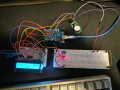
Yo! I wanted to do a project where I use an RTC, a DHT11 and an LCD to display the current time/date and temp/humidity. I started with trying to output to the serial monitor from the DHT11 and RTC, which worked out competley fine, and now I tried to make a simple Hello World display text on the LCD, but I've been going at it for a couple of hours with no results.

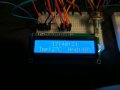
The only thing I succesfully did was turning it on, turning the backlight on, and making the potentiometer work with the contrast (but only the upper row works?). I'll attach below the code that I used, and some relevant pictures.


Arduino Docs lcd code (changed a bit):
#include <LiquidCrystal.h>


LiquidCrystal lcd(12, 11, 5, 4, 3, 2);

void setup() {
  lcd.begin(16, 2);
  lcd.clear();
  delay(500);
  lcd.print("A");
}

void loop() {


}

Now, that is changed a bit, but I also used the default code from the arduino docs. I do not think/see an issue with the hardware wiring, but alas.IMG_20250322_170400.jpgIMG_20250322_170443.jpgIMG_20250322_170520.jpg


If you have any idea/want to see something clearer, respond to this post or shoot me a message on discord: "verd.

I just wanna finish this project lol. (sorry for bad photos/english, the works.)
 

Thread Starter

verd

Joined Mar 22, 2025
5
i <Mod: Obsenity deleted> the code highlight so bad ahaha.
 
Last edited by a moderator:

MrChips

Joined Oct 2, 2009
34,628
You cannot just push jumpers into the holes of the LCD module, that does not guarantee a good electrical connection. You need to solder header pins to those holes and then insert those LCD pins into your protoboard.
Good eye. I didn't even notice that.
 

Thread Starter

verd

Joined Mar 22, 2025
5
You cannot just push jumpers into the holes of the LCD module, that does not guarantee a good electrical connection. You need to solder header pins to those holes and then insert those LCD pins into your protoboard. Make sure your RW signal is low

i did do just that lol, I didn't have a soldering kit by hand but i guess ill get a spare breadboard and a soldering kit and get to it, in the meanwhile ill try to write the data to an excel or whatever, thanks so much,if not for your comment i would've just beaten my head against a wall for a couple more days lol.
 

dendad

Joined Feb 20, 2016
4,635
I use the I2C LCD displays in a lot of projects. (also I2C OLED displays)
1742683031078.png
The correct library for the I2C display will need to be included. "LiquidCrystal_I2C"

They only use 2 I/O pins and those are shared with other I2C devices.
And I second @sagor 's comment. You need to solder the pins onto the LCD.
 

SamR

Joined Mar 19, 2019
5,470
I used 2 wire serial connections to drive them. Whole lot easier than all those wires. Can't recall but I think there was a communication module board soldered onto the display module. You still need the power and backlight wires as well. Been a few years ago...
 

dendad

Joined Feb 20, 2016
4,635
Have a look at this web site for a good intro to the I2C LCD info.
https://lastminuteengineers.com/i2c-lcd-arduino-tutorial/

I get the displays from Ebay, but they are also available from other places at maybe a higher cost.
One beauty of the I2C bus is a number of different devices all share the same 4 wires, Gnd, +5V, SDA and SCL. On my PCBs, there are at least one (but sometimes 2) I2C connectors using 2.54mm JST connectors. Here is my Arduino VFO that has been added to many radio transceivers, replacing the fixed crystal frequencies with tunable ones. The "DISPLAY" connector is the I2C bus, and the on board SI5351 sub board is also on the I2C bus.
1742713109709.png
And if I want, I can add multiple displays on the same bus as long as they have separate addresses.
I would really advise you to try the I2C displays, there are a lot less wires to worry about.
 

Thread Starter

verd

Joined Mar 22, 2025
5
Jesus Christ, y'all rock.

Seeing your comments, I asked my dad to buy a soldering kit (and a spare bread board cause I thought I'd solder the header pin & the lcd directly on a board ? ¿ ). They arrived yesterday and the breadboard just today.

Et voila:IMG-20250325-WA0002.jpg the shoddiest solder work you have ever seen, but if it works, it works.

I saw your comments about using a different library, but every example I saw didnt specify any pins in the code? and the lcd modules some people showed had only 4 pins? I find it a bit confusing and stuck with the normal LiquidCrystal.h library.

Ended up using just this piece of code:

basic lcd hello world code:
#include <LiquidCrystal.h>

const int rs = 12, en = 11, d4 = 5, d5 = 4, d6 = 3, d7 = 2;
LiquidCrystal lcd(rs, en ,d4, d5, d6, d7);

void setup() {
  // put your setup code here, to run once:
  lcd.begin(16, 2);
  lcd.print("hello, world!");

}

void loop() {
  // put your main code here, to run repeatedly:

}
spaghetti wires:eek:

and after a long wait from me, i finally made the LCD display work!IMG-20250325-WA0007.jpg

*No soldering iron silicone caps were harmed in the making of this project (lie).

Now time to add the rtc module, dht11 and display the time, temp and humidity on this bad boy, thanks everyone for the comments!

Also ignore the spaghetti wires, I have some better jumper wires on the way.
 

nsaspook

Joined Aug 27, 2009
16,250
Jesus Christ, y'all rock.

Seeing your comments, I asked my dad to buy a soldering kit (and a spare bread board cause I thought I'd solder the header pin & the lcd directly on a board ? ¿ ). They arrived yesterday and the breadboard just today.

Et voila:View attachment 345326 the shoddiest solder work you have ever seen, but if it works, it works.

I saw your comments about using a different library, but every example I saw didnt specify any pins in the code? and the lcd modules some people showed had only 4 pins? I find it a bit confusing and stuck with the normal LiquidCrystal.h library.

Ended up using just this piece of code:

basic lcd hello world code:
#include <LiquidCrystal.h>

const int rs = 12, en = 11, d4 = 5, d5 = 4, d6 = 3, d7 = 2;
LiquidCrystal lcd(rs, en ,d4, d5, d6, d7);

void setup() {
  // put your setup code here, to run once:
  lcd.begin(16, 2);
  lcd.print("hello, world!");

}

void loop() {
  // put your main code here, to run repeatedly:

}
spaghetti wires:eek:

and after a long wait from me, i finally made the LCD display work!View attachment 345329

*No soldering iron silicone caps were harmed in the making of this project (lie).

Now time to add the rtc module, dht11 and display the time, temp and humidity on this bad boy, thanks everyone for the comments!

Also ignore the spaghetti wires, I have some better jumper wires on the way.
You Rock and now, you are addicted.

Welcome to the Electronic Junkie world.
 

Ya’akov

Joined Jan 27, 2019
10,226
Jesus Christ, y'all rock.

Seeing your comments, I asked my dad to buy a soldering kit (and a spare bread board cause I thought I'd solder the header pin & the lcd directly on a board ? ¿ ). They arrived yesterday and the breadboard just today.

Et voila:View attachment 345326 the shoddiest solder work you have ever seen, but if it works, it works.

I saw your comments about using a different library, but every example I saw didnt specify any pins in the code? and the lcd modules some people showed had only 4 pins? I find it a bit confusing and stuck with the normal LiquidCrystal.h library.

Ended up using just this piece of code:

basic lcd hello world code:
#include <LiquidCrystal.h>

const int rs = 12, en = 11, d4 = 5, d5 = 4, d6 = 3, d7 = 2;
LiquidCrystal lcd(rs, en ,d4, d5, d6, d7);

void setup() {
  // put your setup code here, to run once:
  lcd.begin(16, 2);
  lcd.print("hello, world!");

}

void loop() {
  // put your main code here, to run repeatedly:

}
spaghetti wires:eek:

and after a long wait from me, i finally made the LCD display work!View attachment 345329

*No soldering iron silicone caps were harmed in the making of this project (lie).

Now time to add the rtc module, dht11 and display the time, temp and humidity on this bad boy, thanks everyone for the comments!

Also ignore the spaghetti wires, I have some better jumper wires on the way.
Welcome to AAC.

Just a couple of comments:

1. The only thing worse than a breadboard is not using one.

A breadboard is flaky, promotes errors, and has terrible electrical characteristics—but for the early stages of prototyping they are the only sensible option. Projects that feature high current, high frequency, high part count, susceptibility to noise, or operation in an environment that experiences extremes, or extreme swings in, ambient temperature of humidity are likely act unpredictably or not work at all.

This can be mitigated with a few best practices:

  1. Do not use cheap boards or jumpers. Don’t even let them hang around, chuck them in the e-waste bin—seriously. Don’t let them tempt you by suffering them to live.

  2. Do not use breadboard for project that will be put into “production”. Once you have worked out the project, transfers it to a protoboard with soldered connections. Better yet, have a PCB made for it. Breadboards should never be used for anything that you count on being operational without twiddling.

2. Use silicone insulated jumpers and wires.

Silicone does cost a bit more but it is worth every penny. As jumpers they are very flexible and will not tangle together without some herculean effort on your part to interleave them. This makes tracing wires much easier and can eliminate the pilot error sort of failure where you check your wiring some large number of times yet miss the (when seen) obvious error.

For wiring on protoboards and elsewhere when soldering will be used, the ease of stripping and complete immunity to meltback—that is, the tendency for PVC and other low melting point jacks to shrink exposing much more of the bare wire than intended which can lead to inadvertent connects, some times catastrophic and always looks ugly.

Good luck with your projects—the time taken in careful arrangement of components and connections will pay dividends much greater than you might expect, and ignoring it will most certainly have you cursing the names of Ohm, Volta, Ampere, Faraday, and so many others who made it possible for you to get so tangled up in a rat’s nest of wiring you are considering skipping town and living a hobo’s life.
 

nsaspook

Joined Aug 27, 2009
16,250
Oh, and don't forget to read about and use using filter (energy), bypass and decoupling (very important) capacitors on your projects. Leaving them out has been a demon in many a early project for beginners.

https://www.protoexpress.com/blog/decoupling-capacitor-use/

https://e2e.ti.com/blogs_/archives/...e-decoupling-capacitor-is-it-really-necessary
Before working as an applications engineer, I worked as an IC test development engineer here at TI. One of my projects was to characterize an I2C temperature sensor. After writing some software, I threw together a hand-wired prototype board. I was in a hurry, so I left off that pesky decoupling capacitor. Who needs it, right?

I collected data for about a week, and none of my results matched expectations. I made numerous changes in an attempt to improve performance, but nothing worked. Finally, I decided to add the decoupling capacitor. As you might expect, this solved the issue.

This got me thinking…do we always need decoupling capacitors? What do they really do?
https://resources.altium.com/p/bypass-and-decoupling-capacitor-placement-guidelines
Decoupling Capacitor and Bypass Placement Guidelines
 
Last edited by a moderator:

Thread Starter

verd

Joined Mar 22, 2025
5
Hey again! I'm reading all of your comments and learning a lot, imma keep comming back to this post when starting new projects, but for now I gotta show the finished product.
426611149-83d507e8-c5ee-4b35-b003-9795930082c1.jpg426611234-6b472862-c225-4d2c-ab53-57ab78877ecb.jpg
The thing i set off to do, finally done, and it was so easy after I got done with soldering, the code was easy to implement and the circuit not too hard to make. Don't worry about decoupling capacitors and other stuff like that, the circuit was powered on for legit 15 mins, I looked at it, I took photos, showed a bunch of friends, then uploaded it on github and dismantled it.

Onto the next projects, thanks a lot again for the help everyone!

github repo link if u wanna look at my code and my horrible horrible schematic.
https://github.com/dariusrotaru/Arduino_Led_Clock.git
 

Attachments

Top