Hi everyone.
I've been using a nanoVNA to measure complex impedance of some components (by series, shunt and shunt-through methods).
At 100 MHz, a simple 350 nH handmade air core inductor (0.04 ohm DCR) shows quite high resistive component, about 30~60 ohm.
The reactive component does seem about right (inductance falls just a little bit, to about 320 nH).
My problem is understanding where the high resistive loss come from.
There're no losses due to hyteresys or eddy currents, and the skin effect is not enough to be the root cause (at 100 MHz, DCR should raise by a factor of 40, but still should be on the order of 1 ohm).
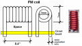
The inductor is a simple 7 turn rectangular section using pvc insulated 0.5 mm/AWG24 diameter wire.
At 10 MHz, I get about 0.5~1.5 ohm.
Thanks in advance for any clue or help.
I've been using a nanoVNA to measure complex impedance of some components (by series, shunt and shunt-through methods).
At 100 MHz, a simple 350 nH handmade air core inductor (0.04 ohm DCR) shows quite high resistive component, about 30~60 ohm.
The reactive component does seem about right (inductance falls just a little bit, to about 320 nH).
My problem is understanding where the high resistive loss come from.
There're no losses due to hyteresys or eddy currents, and the skin effect is not enough to be the root cause (at 100 MHz, DCR should raise by a factor of 40, but still should be on the order of 1 ohm).
The inductor is a simple 7 turn rectangular section using pvc insulated 0.5 mm/AWG24 diameter wire.
At 10 MHz, I get about 0.5~1.5 ohm.
Thanks in advance for any clue or help.