Anyone have good circuit they can post -Solar garden light issue

Thread Starter

hhsting

Joined Apr 25, 2024
395
Briefly.
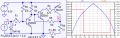
When the solar cell is below .5 volts Q1 transistor is OFF which allows Q2 to conduct which then turns ON Q3.
When the solar cell is above appx .52 volts Q1 turns ON which then turns OFF Q2 and Q3.
The circuit is known as a schmitt trigger. It will rapidly switch ON or OFF when activated by those voltages listed.
R6 is added to limit the current to 100ma on the LED, adjusted for the small voltage loss across Q3 (appx 200mv).
Circuit verified on the breadboard with the components listed.
I was after how you derived resistor values and why.
 
If you are using 12V to avoid the voltage drop in the wiring, and then using a linear regulator to drop the voltage to 3V, then all you have done is increased the losses (by starting with a high voltage) and concentrated them in one device instead of spreading them out across all the wiring.
Use something like the popular LM7805 5 volt regulator. With the exception in your case, needing 3 volts, I believe would be a LM7803. I'm pretty sure they make them in 3 volt. As you can see by the part numbers that the last 2 digits is the regulated output. They are very simple to hook-up only 3 connections. They look like a transistor but it's actually an IC regulator. There's a mounting hole for a heat-sink if you're running a bit of current through the device. You'll need to add up your lights total current. Also for the AC adapter you'll be using. If you've got 5 lights at 100ma you are already at 1/2 an amp. 500ma is a good load at 3 volts, so you may need to heat-sink the device.
 
As far as those solar yard lights go, I always tossed the thought in my mind, of having one separate power source. Have a solar cell and proper capacity battery in one unit that will power 6 or more yard lights. I know it would defeat the wireless aspect of the product. It would keep them going all night and at the same brightness. In order to place your yard lights in a nice symmetrical way throughout your pathways and whatnot, you'll always end up with some not in the ideal position for sun exposure. Therefore, not fully charging some lights. Another idea I have, is to use one of them decorative old-fashioned garden windmills that stand about 6 feet tall. Incorporate a DC generator to charge your yard light battery. Maybe both, solar/wind.
 
No relays please. No ics please
Hahaha Anti-relay & Anti-IC Well, I'm pro-transisor! You can use a basic transistor as a switch. Emitter tied to ground is a common transistor switch configuration to turn on low current loads. Commonly used to drive relay coils. You might be against it, however. LOL
 

sghioto

Joined Dec 31, 2017
8,757
I was after how you derived resistor values and why.
R1 is an arbitrary value to limit the base current in Q1, seemed about right considering the low output voltage from the solar cell to turn the LED OFF.
R3,R4 and R5 are selected between a 10 and 20 to 1 current ratio, meaning the collector current is 10 to 20 times the base current.
This is based on the hfe or dc gain of the transistor at different current levels.
R2 was determined by experimentation. For Q1 to conduct enough to shut off Q2 required .64 volts at the base of Q1.
R2 increased the voltage on the base of Q1 appx .12 volts so when the cell is at .52 volts the LED is OFF.
Actually a BC327 is a better choice for Q3 with the resistor values listed. Schematic modified in post #38.
Use the 4.5 volt setting on that power supply listed in post #1.
 

Thread Starter

hhsting

Joined Apr 25, 2024
395
R1 is an arbitrary value to limit the base current in Q1, seemed about right considering the low output voltage from the solar cell to turn the LED OFF.
R3,R4 and R5 are selected between a 10 and 20 to 1 current ratio, meaning the collector current is 10 to 20 times the base current.
This is based on the hfe or dc gain of the transistor at different current levels.
R2 was determined by experimentation. For Q1 to conduct enough to shut off Q2 required .64 volts at the base of Q1.
R2 increased the voltage on the base of Q1 appx .12 volts so when the cell is at .52 volts the LED is OFF.
Actually a BC327 is a better choice for Q3 with the resistor values listed. Schematic modified in post #38.
Use the 4.5 volt setting on that power supply listed in post #1.
I have 3vdc not 4.5 vdc supply.
 

Thread Starter

hhsting

Joined Apr 25, 2024
395
That power supply you listed has 8 settings, are you not using it?
Yea but when i run simulation i get 4.5 vdc at r6 not 3vdc?? I get current of 420 ma. Ltspice r6. Led is rated for 3vdc at 100 ma

Also how to calculate voltage between R3 and R5, R5 and R6?
 
Last edited:

sghioto

Joined Dec 31, 2017
8,757
Yea but when i run simulation i get 4.5 vdc at r6 not 3vdc?? I get current of 420 ma. Ltspice r6. Led is rated for 3vdc at 100 ma
The simulation is showing the circuit with no losses which doesn't happen in the real world.
Change R6 to 15 ohm and simulate the LED as a 30 ohm resistor. No way it should show 420ma.
 

Thread Starter

hhsting

Joined Apr 25, 2024
395
The simulation is showing the circuit with no losses which doesn't happen in the real world.
Change R6 to 15 ohm and simulate the LED as a 30 ohm resistor. No way it should show 420ma.
how to calculate voltage between R3 and R5, R5 and R6?
 

sghioto

Joined Dec 31, 2017
8,757
At the junction of R5 and R6 it's either 0 or 4.5 volts, meaning Q3 is either fully ON or not.
At R3 and R5 it's either 0 or appx .65 volts, meaning Q1 is either fully ON or not.
 

Thread Starter

hhsting

Joined Apr 25, 2024
395
At the junction of R5 and R6 it's either 0 or 4.5 volts, meaning Q3 is either fully ON or not.
At R3 and R5 it's either 0 or appx .65 volts, meaning Q1 is either fully ON or not.
Ah. What i dont get is if Q1 is off that turns on Q2. But how does Q2 when on turns on Q3? What role does 470 ohm resistor, r5, and r6 play??
 

sghioto

Joined Dec 31, 2017
8,757
Ah. What i dont get is if Q1 is off that turns on Q2. But how does Q2 when on turns on Q3? What role does 470 ohm resistor, r5, and r6 play??
Then you need to study how NPN and PNP transistors work as switches.
R6 is simply to limit the current at 100 ma through the LED as mentioned in post #40.
 

Thread Starter

hhsting

Joined Apr 25, 2024
395
Then you need to study how NPN and PNP transistors work as switches.
R6 is simply to limit the current at 100 ma through the LED as mentioned in post #40.
I understand how npn and pnp
Then you need to study how NPN and PNP transistors work as switches.
R6 is simply to limit the current at 100 ma through the LED as mentioned in post #40.
i am aware of how npn and pnp functions.

here is where i get stuck:

When voltage is 0.6V then Q1 base to collector is < 0.7V so it is off. Between R3 and R5 is 4.5vdc since Q1 is off. This causes Q2 turn on.

now Q3 is off at this point. The voltage between R5 and R6 is 0V Q3 is off. So then theur is current thru R5 (4.5V)/R5 which then causes current thru 470 .

i just dont see how Q3 is turning on? Please can you eloborate
 

sghioto

Joined Dec 31, 2017
8,757
I am aware of how npn and pnp functions.
If you did you wouldn't be asking these questions and I'm not trying to be sarcastic or mean about it just saying.
OK, will try and explain how Q3 is turned on.
When Q2 starts to conduct current flows through R4 and the base-emitter junction of Q3.
As Q3 begins to conduct it feeds voltage back through R5 increasing the bias on Q2 which causes the switching to act rapidly giving a definitive ON-OFF operation.
At this time Q2 and Q3 are both in saturation mode.
BTW there is never 4.5 volts at the junction of R3-R5 because the emitter-base junction of Q2 clamps the voltage at appx .7 volts max.
 
Last edited:

Thread Starter

hhsting

Joined Apr 25, 2024
395
If you did you wouldn't be asking these questions and I'm not trying to be sarcastic or mean about it just saying.
OK, will try and explain how Q3 is turned on.
When Q2 starts to conduct current flows through R4 and the base-emitter junction of Q3.
As Q3 begins to conduct it feeds voltage back through R5 increasing the bias on Q2 which causes the switching to act rapidly giving a definitive ON-OFF operation.
At this time Q2 and Q3 are both in saturation mode.
BTW there is never 4.5 volts at the junction of R3-R5 because the emitter-base junction of Q2 clamps the voltage at appx .7 volts max.
Great i try to build in on pcb. Just one question if i want to use ziner diode as stable 3VDC supply how can I do that with current circuit?
Thanks
 
Top