Any ideas to stop a huge negative voltage spike during mosfet shut off?

Tonyr1084

Joined Sep 24, 2015
9,744
Given that large electrolytic caps consist of coiled sheets of foil, how much inductance does each cap have?
Inductors require current flowing through them. Since this is a DC circuit - capacitors do not conduct. They charge and discharge but there is no inductance. At least none that I know of. School me if I'm wrong. Inductors are not capacitors and caps are not inductors. While each can build a charge and discharge - I don't think you can assume a cap is acting like an inductor.

Perhaps the orientation of the flyback diode is in backwards. Be careful though. Looks like you're dealing with a lot of power (wattage). Don't burn yourself. Or your house down.
 

Thread Starter

Cfez202

Joined Apr 25, 2018
37
No spikes.
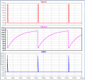
Even 30V transistor works just fine:
View attachment 171323
Thank you for doing this! When I run this same exact circuit I still get the 300v negative spike! What the heck is going on.
No spikes.
Even 30V transistor works just fine:
View attachment 171323
EDIT:
No breadboard, soldering only!
Wiring:
View attachment 171365
Thank you so much for putting this much effort into my problem! This is great.

This is exactly what I have right now and I'm still getting the same spike. I even reduced the number of capacitors to 1 and shortened all wires to the minimum I can physically package. Also if I disconnect the power supply entirely after charging the capacitor, same spike.
Maybe I destroyed the body diode or killed my flyback diode at some point? Something is not functioning I think.
 

Alec_t

Joined Sep 17, 2013
15,160
Inductors are not capacitors and caps are not inductors.
That is the ideal situation. Inductors have parasitic capacitance and resistance. Capacitors have parasitic inductance and resistance. Such inductance may be small, but when the capacitance discharges there is a huge current pulse (current = rate of change of charge). This current pulse induces a voltage in the parasitic inductance, given by the product of the inductance and the rate of change of current.
 
Circuit from post #19 is ok, but need to be "enhanced" with several other elements (snubbers; you already have in your own circuit, post #1. I will be back with a diagram. Be careful for that flywheel diode, at the frequency you'l use needs to disipate lot of power and must be on a heatsink
 
Got it. I posted yesterday in reply to another similar issue here
https://forum.allaboutcircuits.com/threads/exploding-high-current-mosfets.157082/page-2#post-1362409

Just read the information and apply (with some adjustments relativ to your voltage, currents and frequency).
The diode which acts as the flywheel shunting the "negative spike" is DSK1. I insist on using really fast and powerfull diodes, but not SCHOTTKY because they are fragile. At your high frequency you need to use diodes up to probably half of your output current. See how hot the become. Do not try first with high current and only one-two diodes; they will fail and the MOSFET will follow.
 
Ah, and do not try to load the transistor beyond half it's current; that 170A or so is a theoretical current only. For TO247 typical safe currents may be 50-70A using no more than 1/2 duty cycle; for TO220 is in 20-30A range per casing, even if datasheets may say ....260A (yeah)
 

Thread Starter

Cfez202

Joined Apr 25, 2018
37
Got it. I posted yesterday in reply to another similar issue here
https://forum.allaboutcircuits.com/threads/exploding-high-current-mosfets.157082/page-2#post-1362409

Just read the information and apply (with some adjustments relativ to your voltage, currents and frequency).
The diode which acts as the flywheel shunting the "negative spike" is DSK1. I insist on using really fast and powerfull diodes, but not SCHOTTKY because they are fragile. At your high frequency you need to use diodes up to probably half of your output current. See how hot the become. Do not try first with high current and only one-two diodes; they will fail and the MOSFET will follow.
Thanks for this! Going to order the parts and try it out!
In the circuit you posted is CPE1 their equivalent of my big caps? Or does that serve a different purpose? also what kind of diode would you use for DZP1? Just a regular zener with with a voltage a bit above my expected voltage?
 

Danko

Joined Nov 22, 2017
2,247
The Fet needs to turn on and off very quickly (will eventually run PWM at 62kHz) so options like relays or SCRs wont work.
Some conditions:
1. FET should be turns ON when capacitor is almost fully charged.
2. FET should be turns OFF at drain current 10...20A.
3. Frequency of PWM is 62 kHz (160us cycle).
It will executed with 10uF (not 88000uF) ceramic capacitor and about 2% (3us) duty cycle.
And pulse current through diode will not more that 20A (average current will <0.5A).
Average welding current in this case will 1.44A (13A RMS).
See diagram:
upload_2019-3-3_3-16-2.png
EDIT:
On picture we can see one only wire going from driver to FET.
Means it that 24V and 15V (12V) sources already shared common minus?
15V (12V) source should be separate power supply, like wall wart, feeding driver.
From driver to FET should be go two wires:
First from OUT pin to resistor 10 Ohm, already connected to gate lead.
Second from driver ground pin to FET source lead, soldered as close,
as possible to plastic FET case. These wires should be twisted and are no more, than 3" length.
With load resistor 0.1 Ohm:
Pulse on gate should be not shorter, than 30ms, better - 50 ms (for capacitor 88000uF).
With load resistor 1 Ohm:
Pulse on gate should be not shorter, than 300ms, better - 500ms (for capacitor 88000uF).
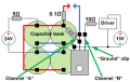
Check oscilloscope connections:
upload_2019-3-3_9-33-7.png
 
Last edited:

Danko

Joined Nov 22, 2017
2,247
Not a single one of these changes effected the negative voltage spike at all. I was sure I just needed a diode to kill the spike but nothing helps. The circuit is so simple I just can't think of anything else I could be doing wrong. Anyone have good ideas to try??
It seems that channel 1 is inverted...
 
Top