Antenna theory

t_n_k

Joined Mar 6, 2009
5,455
I've also built (kits) for 2.4Ghz receivers using 1 pound coffee cans and washer yagi antennas (they can be intimidating looking, much like a Buck Roger's ray gun).
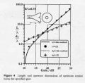
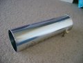
This was a Buck Roger's style 2.4GHz cantenna I made a couple of years ago. I used to search everywhere for a good cylindrical tube for the job. Drove my wife nuts. Some people made them out of Pringles potato chip 'cans'.
 

Attachments

retched

Joined Dec 5, 2009
5,207
Good find.

I ordered a Glenlivet 18yr and Glenfiddich 18yr a few years ago as gifts (I hate the stuff) and I still have the cans.

You just gave me a project. I never considered a cantenna, but I have the parts, and just yesterday I recieved a need for it. Very good, thanks for the solve and inspiration.
 

sceadwian

Joined Jun 1, 2009
499
Some people made them out of Pringles potato chip 'cans'.
The Pringles cantenna's don't work well at all, they'd have to be like 6 feet long to allow any practical gain.

http://flakey.info/antenna/waveguide/

I used to have a PDF that had the absolutely ideal dimensions for a cantenna, that would produce maximum gain over the entire wifi range, I've lost it however. it was between 83 and 96mm's though and the overall length (depending on the outside diameter) was in the range of 5-7 inches. Anything close to this should get you 9-12db of directional gain.

I've seen websites of people using cantennas for long distance wifi links, the main problem being is the time of propagation is so long that it violates timeout limited of the wi-fi protocol. It's an easy registry fix.
 

Wendy

Joined Mar 24, 2008
23,797
The nearest thing I've found on the web to the washer antenna is here. Mine was 3 feet long, used all thread for the core and spacers that were approximately 2.4" long, with 2.4" washers between them. All of this was mounted in a PVC pipe cut to length with end caps, and the yagi antenna was mounted to the center of the end cap. It only superficially resembles the Pringles cantenna, but the principle was the same. It had excellent gain, and was developed by amateur radio. It down converted 2.4Ghz to Channel 3. I used it watch a local microwave TV station in the early 80's.
 
Last edited:

sceadwian

Joined Jun 1, 2009
499
As a waveguide the dimensions of a pringles can DO NOT WORK. I'm sure you got good gain, maybe 3-6db, the true gain on a good cantenna is 12db.
 

Wendy

Joined Mar 24, 2008
23,797
The can portion is drawn slightly oversized, but this is what it looked like. The antenna is 3' long, and the can was a 1 pound Folger's coffee can. There was a second can cut down to make an enclosure, they were tin cans. I don't know if you can get those coffee can styles anymore, I don't drink coffee. It was pretty close to resonant.


How would you like this aimed at your bedroom window. I was in an apartment complex at the time.

And my gain was a lot better than you think, how could you know? Ever build one? I suspect the geometry inside the can doesn't match your mental image either,as this is not a Pringles can.

The actual antenna, all 1.2 inches of it, feed through a hole and had the coax (semi rigid) soldered to the side of the can, with the solid center connector sticking straight up. Basically it was a simple feed horn arrangement. I keep referring to 2.4 inches, thinking about it I'm pretty sure this is off. It was a half wavelength of 2.4Ghz, while the spacers and washers were a full wavelength.

The yagi in front is a very high gain antenna. It helped to have friends in a machine shop, they got one too. The results were impressive, very impressive, I believe the total spec was 12 - 15db (8db for just the can). A later version I build used a modified UHF parabolic with fine screen mesh laid on the inside, but as I had moved I was too far away to get a clean signal anymore, that and curve of the earth. It was rated for 20db gain total.
 

Attachments

Last edited:

sceadwian

Joined Jun 1, 2009
499
The typical cantenna I've seen is grounded to a coax shield and the feed element is a 1/4 wave element stick up into the can 1/4 wavelength from the back of the can and will provide 10db of gain, you can get 12 if it's exactly resonant.

http://www-personal.umich.edu/~nliebman/cantenna.pdf

This isn't the original PDF file that I found but they came up with the ideal diameter which I suddenly remember when seeing was 93.6mms
One thing that irks me is they don't give the length of the can, there was an optimal length to the can and position for the feed element inside the can for best gain, I think it was somewhere in the neirboorhood of 2-3 feet. I wish I could find it because with the proper dimensions it should have had a gain as 12 by itself, which could be increased like you suggested with a parabolic reflector if needed.
 

Tesla23

Joined May 10, 2009
560
Just a couple of points on cantennas:

- 2.45GHz cannot propagate in a circular waveguide with a diameter less than 71.8mm (this is for the TE11 mode - the mode with the lowest cutoff)
- to avoid the TM01 mode at 2.45GHz you want to keep the diameter below 93.7mm (exciting the TM01 mode simply may make the aperture distribution more uneven and cost a little gain, on the other hand the aperture is larger which will increase the gain)
- you normally place the feed a quarter of a guide wavelength from the short circuited end
- the length of the cylinder from the feedpoint to the open end is relatively non-critical, it should be long enough for the higher order modes to die out. Once it is a guide wavelength or two then increasing the length shouldn't have any effect on the gain.
- If your cylinder diameter is smaller than 71.8mm then to have any chance of working it should be shorter rather than longer (as the wave is being attenuated as it passes down the guide).
- the 12dB quoted in the paper is for a uniformly illuminated circular aperture, no simple waveguide can do this, so the 10dB they achieved is probably doing quite well
- an easy way to increase the gain for home brewers is to flare the open end like a horn. If you flare it slowly then each time you double the aperture diameter you increase the gain by about 6dB. There are some numbers on the attached graph (gain in dBi)


(from http://www.ece.uvic.ca/~jbornema/Journals/049-95motl-b.pdf)
 

Attachments

count_volta

Joined Feb 4, 2009
435
Oh wow what an excellent thread. I am learning about radio this semester and it always bothered me that antennas are basically an open circuit, and yet they still work.

Edit: The best explanation of how antennas work that I ever saw.
http://www.scss.tcd.ie/Stephen.Farrell/ipn/background/US-Navy-NEETS/Module10-14182.pdf

I swear all the best electricity books were made for the army and the navy. They concentrate on the concepts rather than the math. The math will come later, its the concepts that really matter.

Seriously just think of the dipole antenna like a capacitor with its plates spread out. It makes sense. And read that pdf.

 
Last edited:

count_volta

Joined Feb 4, 2009
435
As I understand it from this explanation, a monoplane antenna would be connected like this?


You connect the transmitter output to the antenna, and the transmitter ground to the ground plane (earth or whatever) and make sure the antenna is insulated from the ground plane. Is this right? This way its still essentially a capacitor. I'm still learning about this, so please correct me if I'm wrong.
 

count_volta

Joined Feb 4, 2009
435
Could someone please reply and tell me if my understanding of the monoplane antenna is correct in the previous post?

I noticed that the RF forum never has many people browsing it. Weird.
 

Wendy

Joined Mar 24, 2008
23,797
As I understand it from this explanation, a monoplane antenna would be connected like this?


You connect the transmitter output to the antenna, and the transmitter ground to the ground plane (earth or whatever) and make sure the antenna is insulated from the ground plane. Is this right? This way its still essentially a capacitor. I'm still learning about this, so please correct me if I'm wrong.
Actually from a RF point of view I don't think it matters. From a transmitter point of view it can be very important.

Antenna's both transmit and receive, the antenna remains the same, the application differs.
 
Top