Another treadmill repair thread

Status
Not open for further replies.

Thread Starter

gibbon

Joined Nov 20, 2014
5
Hi all, from what I can tell, allaboutcircuits is THE place to go for treadmill repair advice, so here goes;

We have a Prorunner 300z treadmill (of which there is literally no support for online, and in fact barely any acknowledgement of it's existence!) which is about 2 years old and the wife used every day until recently, when it suddenly stopped mid-run.

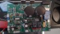
I opened it up and found the 12A fuse blown. I replaced it and turned the machine on, it did it's usual beep-beep, beep-beep, the motor turned briefly and the fuse blew again, big time. I tried again while keeping various items plugged in/unplugged. Ultimately, as long as I kept the main treadmill motor unplugged, it was fine. Unfortunately as I discovered this the hard way, I also noticed some smoke coming from a couple of units that I later identified as IGBTs. I'm no electrical engineer here, so please bear with me.

The motor is labelled as 180v DC, but the control board has outputs labelled M+ and M-, which had outputs of 220V AC (mains power) and 115V DC respectively, relative to the treadmill frame. I have no idea if this is normal. Would a DC motor ever want two different types of input? It has two brushes, but why does it need two inputs, when it has a separate ground? The brushes looked OK, and the motor turned freely. While it did turn briefly before blowing the fuse, I was not able to get it to run off a car battery (of which the charge state I can't guarantee, to be fair)

I read that most of the problems are caused by the MOSFETs and other transistor bits and pieces. I replaced both the IGBTs, there is a bridge diode that tested out OK so I didn't touch it, and a ultra fast dual diode which also appeared to be OK, so I didn't replace. I don't know what the function of these parts are, other than that they appear to be related to the motor control.

I turned the power on and only got a single pair of beeps. beep-beep. The fuse didn't blow, but the motor didn't turn, even though it had the same outputs at the M+ and M- as before. I tried giving it a spin to get it going but no luck. This was with the belt disconnected.

There is a transformer feeding the board which has a mains feed input, and two outputs, 10v and 15v AC. Both of which only gave about 1 volt AC through my multimeter. What's more confusing is that the plug which one of the outputs was supposed to connect to already had mains power at it! I'm thinking that there's a 220VAC, 10VAC and 15VAC section of the board for carrying out various functions, and somehow the mains power has gotten where it shouldn't - by shorting through a relay perhaps? Interestingly enough the display unit still works, so presumably the mains power never made it up there

So that's where I am now... unfortunately I suspect that the answer is going to be "it's buggered, replace everything" - this was a fairly expensive treadmill and it's only a couple of years old, the wife is very upset and the seller is AWOL, very disappointing. Thanks for reading!
 

MaxHeadRoom

Joined Jul 18, 2013
30,658
Sounds like you have done some extensive testing so far.
What is the part No's of the devices replaced?
Post a pic of the board if possible.
Max.
 

CharlesWMcDonald

Joined May 16, 2019
235
This is a mains connected system and the DC for the motor is derived through a bridge rectifier. Since the neutral of the mains is connected to earth ground at your breaker box the output of the bridge rectifier will have an AC component. The motor only sees the DC. This is a very dangerous circuit to work on because the reference point for any measurement in the control circuit rides on top of high voltage AC.

It is likely that replacing the motor would have fixed the treadmill. However, since you have had smoke from the circuitry you have probably damaged other components as well.

Time to get a new treadmill. Unless you are very experienced with electricity you will likely get yourself killed working on this device.
 

Thread Starter

gibbon

Joined Nov 20, 2014
5
Thanks for the replies (and the warning!)

Here's a picture of the board. The IGBT's were some flavour of F20N60, of which the exact part number isn't in front of me, I couldn't find the EXACT identical replacement in terms of prefix and suffix, and Installed a pair of FGAF20N60SMD items. Feel free to tell me that the prefix and suffix are the most important part of the whole thing... Please remember I am absolutely not an electrical engineer.

Charles I am doing my utmost not to kill myself... you say that the motor will only see DC, I currently have an AC output on one of the two motor outputs - is that an indication that the bridge rectifier has failed? I looked up a way to test it with a multimeter and it seemed to be behaving as advertised

Unfortunately even the motor appears to be something of a bespoke item, the part number is YA225AP, which yields absolutely nothing in terms of internet searching. The company that sells these things is failing to answer my emails, you'd think they'd be in the know with regards to how to get spares for them. Unfortunately the machine cost us over $2000NZD so it's a hill that I'm choosing to die on for now
 

Attachments

CharlesWMcDonald

Joined May 16, 2019
235
In a line connected bridge rectifier the neutral input is grounded at your breaker box. On each half cycle of the input sine wave one of the outputs will be connected to neutral and the other to hot. So on one of the negative half cycle the negative output of the bridge will have high voltage and the positive side will be near ground potential. The DC output will be riding up and down on a sine wave when referenced to ground. If you measure across the bridge output you will only see the DC voltage with a little ripple depending on how well it is filtered. The DC is used to run the electronics and the motor. The AC is a side effect of how the circuit is wired, it is not used to run the motor.

The reference point for any measurement in the electronics or at the motor is the negative terminal of the bridge rectifier. The fact that the output terminals of the bridge have high voltage relative to ground is what makes it so dangerous. Everything on the output side of the bridge will have AC voltage relative to chassis and earth ground. It doesn't mean the bridge is defective, although the bridge could be defective but not necessarily due to AC on the output side.

Not having a good understanding of the operation of this circuit can get you killed. If you proceed, I suggest the following preliminary steps:
  1. Get right with God.
  2. Tell your family goodbye.
  3. Make sure your insurance is paid up.
 

MaxHeadRoom

Joined Jul 18, 2013
30,658
Carefully measure the voltage at the motor terminals, you could also substitute the motor for a incandescent lamp to see if any fault shows up.
How do you know it is AC at the motor terminals, this will normally be a DC PWM operated output.
Measure the output of the bridge also.
Any high voltage DC should be measured/referenced from the bridge -ve terminal.
A simple test on the motor is to hook it up to a source such as an automotive battery for a rough test.
Max.
 

Thread Starter

gibbon

Joined Nov 20, 2014
5
I haven't gotten back to measuring anything yet - but I measured previously using a standard multimeter. I got the AC reading by setting the multimeter to AC voltage, and with the negative lead of the meter on the neutral wire (I think - the green and yellow wire from the motor which is earthed to the treadmill chassis), and measuring at the output terminal on the board (my memory is fading, I can't remember if it was M+ or M-. BUT, the other terminal did not give the same result, instead I had to switch to DC and it gave me a measurement of 115V or thereabouts.

Having said that, I read Charles' post (and re-read it a few times), it sounds like I am tricking myself by measuring relative to the treadmill chassis, as you have both stated that this will give me a (false? somehow?) AC reading, whereas measuring vs the bridge neutral will give me a DC reading, which is supposedly what the motor sees. Shouldn't that be the case for both the motor outputs though?

The motor didn't work when hooked up to a battery, but that same battery went on to not be able to start my car, so it's since been charged and I'll try again. But just to clarify, I've got 3 wires going to the motor, and obviously only two battery terminals, err... how do I hook it up exactly? I may have done it wrong. Actually can we just go back a few steps and could someone please explain to me why the motor needs two inputs as well as an earth in the first place?

As you're probably starting to discover, I have next to no experience with AC circuits, and only a "wire a car stereo" level of DC knowledge. Thanks again for your help
 

MaxHeadRoom

Joined Jul 18, 2013
30,658
@gibbon As per post #6, you measure any high voltage DC with reference to the bridge -VE terminal.
The low voltage control will be isolated in this case as it has a LV transformer.
Max.
 
as you have both stated that this will give me a (false? somehow?) AC reading
No, the AC is real!

explain to me why the motor needs two inputs as well as an earth in the first place?
The motor should have two wires for the winding of the rotor. The additional wire should be ground. It needs this ground because the DC is not isolated from the line voltage and you need the safety protection of grounding the motor case in the event of leakage current inside the motor.
 

Thread Starter

gibbon

Joined Nov 20, 2014
5
Charles as much as you are a huge wet blanket with your safety concerns, I'm starting to see things your way. To quote a workmate, my head "isn't the right shape" to understand AC. Like most people I enjoy solving problems and learning on the way but in this case I think the wife would rather have a professionally fixed treadmill than a dead husband for her birthday. I'll give the local electronics repair place a call in the morning. Thanks again for the help everybody!
 
Sorry about that but even though I don't know you I'd rather have you alive. If you have any low voltage circuit questions I'll try to be more accommodating.
 

JoeJester

Joined Apr 26, 2005
4,390
Charles, when you suspect someone's skills are not so safety orientated, don't respond.

I've quit worrying about someone who may commit suicide by Darwin.

The ass you save may be your own. I've said that many times to people who worked for me about the requisite knowledge of where dangerous potentials and currents exist.
 
If someone doesn't know they are doing something dangerous and I can teach them then I will do what I can. If they know it is dangerous and continue to do something foolish, there is nothing I can do. I think the TS has a real interest in electronics and will have a chance to learn. Someday he may become proficient enough to understand the risk and know how to safely troubleshoot these circuits. In the meantime I hope to hear from him again on another interesting but safer topic.

I once held a position as a Research and Development Engineer designing line connected SMPS. I'm confident in my abilities and believe I have a responsibility to pass on the knowledge.
 

JoeJester

Joined Apr 26, 2005
4,390
Unfortunately, you can tell them all you want, you can point them to the body of evidence about electrical shock, but you can't make them apply such knowledge to what they are doing.

I certainly appreciate you sharing your knowledge in these forums. I've come to realize, and it is the common repair shop's philosophy their first choice is the electrolytic capacitors or do all the quick fixes known vice troubleshooting as that takes too much time. I'm sure you have read where someone had replaced all the electrolytics and yet the problem remains.

Share away. Many times it will fall by the wayside, but it will be recorded and hopefully read and adhered to.
 
Treadmill repair question.

I have an old Sole F85 that has been acting up of late. A variety of things have happened:

1. Shuts off abruptly esp if I press incline.

2. Won’t switch on. I have more success there if I have nothing else plugged into the power bar.

3. Console flashes.
 
Status
Not open for further replies.
Top