 Facebook
 Google
 GitHub
 Linkedin
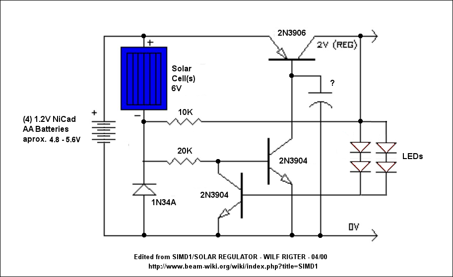
The following circuit is a bastardized version of a SIMD1 / Solar Regulator, and it may be more true than not. That's why I am looking for opinions on its functionality as well as tweaking advice.
Original Circuit Description
SIMD1 / Solar Regulator
The SIMD1 was enhanced in the Solar Regulator version which supplies a constant 2V after
triggering and permits driving LEDs without using current limiting resistors with constant
brightness. Note that you can use this Low Drop Out (LDO) linear regulator for various
applications but like all linear regulators it is "lossy". This is not a problem for controlling LEDs
since they would otherwise use "lossy" resistors but for motors it is a different story.
Try this new SIMD1 / Solar Voltage Regulator for use with blinking LED circuits (pummers). It
turns on when it gets dark, just like a D1 but the output voltage is regulated to about 2V
(depending on the reference LED Vf).
The SIMD1 / solar regulator circuit draws no current during charging and when turned on, it
draws less than 100uA with a maximum 10ma output current. The regulator provides constant
LED brightness during the discharge and turns off when 1F solar capacitor voltage drops below
the LED turn on voltage. The LED used for voltage reference in the solar regulator feedback loop
and the LEDs used for the flasher must be the same high efficiency type to match the forward
voltage specs. This circuit is ideal for supplying voltage to a Bicore or 74HC14 LED flasher since
it eliminates the LED current limiting resistors and greatly reduces current consumption of the
HC flasher circuits.

One interesting alternative would be to substitute a 5V NiCad (4 cell) battery for the 1F supercap
which acts to increase the storage capacity many fold for use with flag waver motors,
pendulums, etc. With higher load current, the 100K resistor may be replaced with 20K for up to
50 ma output current. The quiescent current of the regulator remains very low and is
proportional to the load current for high efficiency operation during discharge.
Charging
The solar cell charges a 1F capacitor through a 1N34A Germanium diode to a maximum voltage
of 5.5V. While the charging current flows through the diode the voltage at the cathode (stripe) is
about 100 mV negative with respect to the 0 V line. This negative voltage is applied through a
100K resistor to the base of a 2N3904 NPN transistor Q1 and holds that transistor off. This cuts
off the base current for the 2N3906 transistor (PNP) Q2 and the output of the regulator will be
zero volts.
Switching
Rapid switching is very important in this type of circuit because a circuit that is half on draws
power, draining the capacitor, but performs no useful work. On the SIMD1/ Solar Regulator, the
output snaps on and off.
At the end of the charging cycle, when the light on the solar cell decreases, the negative
terminal of the solar cell starts to become more positive than the 0V line. The base of the NPN
Q1 must be at about +500 mV (positive) with respect to the emitter which is connected to the 0
V line, before it turns on and turns on the rest of the regulator. That usually happens in the
evening but can be simulated by cupping your hand in front of the solar cell.
When Q1 turns on, the PNP transistor 2N3906 - Q2 receives base current and it starts to turn on.
The regulator output voltage at the collector of Q2 increases to about + 2V when the red LED
starts to turn on and to supply current to the base of NPN transistor 2N3904 - Q3. When Q3
turns on it "robs" base current from Q2. This in turn controls the base current for Q2 and the
regulator output will stabilize at +2 V. The 10K resistor from the regulator output to the
negative terminal of the solar cell provides positive feedback to the regulator turn on by loading
the solar cell down so that it's output voltage drops even more and the regulator "snaps" on.
Note that the red LED is used for reference voltage only and does not actually light up.
Discharging
The output voltage at the collector of Q2 remains at 2V while the voltage on the main capacitor
can range from a full charge at 5.5V to 2.1V at the end of the discharge cycle. If no load is
attached to the regulator the capacitor voltage will drop very slowly because of leakage and a
small amount of current required for the active regulator (<50 uA). When a HC chip like a
74HC240 or 74HC14 is powered from the 2V regulated output, the current for that chip is also
very low.
If the HC chip has a LED connected to the output which the same type of LED that is used for
reference, then the current will be limited by a small voltage drop on the HC driver output. Since
the regulated voltage is constant the brightness of the LED is also constant.
When the voltage on the 1F cap drops below 2V, the regulator reference LED turns off and the
base currents of Q1 and Q2 increase discharging the remaining charge on the cap and turning
any attached circuit rapidly off. At some point the voltage of the solar cell even in dim light is
higher than the remaining charge on the capacitor and if there is sufficient light (usually in the
morning) the charging cycle repeats all over again. If the Sun is bright and the solar cell was
shielded by your hand, then exposing the solar cell to the bright sunlight generates enough
power to turn the regulator off and force the circuit back into the charging cycle.
The PowerSaver Flasher uses capacitive output coupling to produce brighter shorter flashes and
has a much lower average current drain than standard bicore or 74HC14 flashers. The PS Flasher
with one LED circuit (2 LEDs) runs all night from a 1F cap charged to 5.5V. Up to 12 LEDs can be
controlled with one 74HC14 flasher and probably would run for 2 hours from a full charge. Use a
range of timing resistors between 1M and 4.7M for each oscillator to give a random light show
appearance.
Original Circuit Description
SIMD1 / Solar Regulator
The SIMD1 was enhanced in the Solar Regulator version which supplies a constant 2V after
triggering and permits driving LEDs without using current limiting resistors with constant
brightness. Note that you can use this Low Drop Out (LDO) linear regulator for various
applications but like all linear regulators it is "lossy". This is not a problem for controlling LEDs
since they would otherwise use "lossy" resistors but for motors it is a different story.
Try this new SIMD1 / Solar Voltage Regulator for use with blinking LED circuits (pummers). It
turns on when it gets dark, just like a D1 but the output voltage is regulated to about 2V
(depending on the reference LED Vf).
The SIMD1 / solar regulator circuit draws no current during charging and when turned on, it
draws less than 100uA with a maximum 10ma output current. The regulator provides constant
LED brightness during the discharge and turns off when 1F solar capacitor voltage drops below
the LED turn on voltage. The LED used for voltage reference in the solar regulator feedback loop
and the LEDs used for the flasher must be the same high efficiency type to match the forward
voltage specs. This circuit is ideal for supplying voltage to a Bicore or 74HC14 LED flasher since
it eliminates the LED current limiting resistors and greatly reduces current consumption of the
HC flasher circuits.
One interesting alternative would be to substitute a 5V NiCad (4 cell) battery for the 1F supercap
which acts to increase the storage capacity many fold for use with flag waver motors,
pendulums, etc. With higher load current, the 100K resistor may be replaced with 20K for up to
50 ma output current. The quiescent current of the regulator remains very low and is
proportional to the load current for high efficiency operation during discharge.
Charging
The solar cell charges a 1F capacitor through a 1N34A Germanium diode to a maximum voltage
of 5.5V. While the charging current flows through the diode the voltage at the cathode (stripe) is
about 100 mV negative with respect to the 0 V line. This negative voltage is applied through a
100K resistor to the base of a 2N3904 NPN transistor Q1 and holds that transistor off. This cuts
off the base current for the 2N3906 transistor (PNP) Q2 and the output of the regulator will be
zero volts.
Switching
Rapid switching is very important in this type of circuit because a circuit that is half on draws
power, draining the capacitor, but performs no useful work. On the SIMD1/ Solar Regulator, the
output snaps on and off.
At the end of the charging cycle, when the light on the solar cell decreases, the negative
terminal of the solar cell starts to become more positive than the 0V line. The base of the NPN
Q1 must be at about +500 mV (positive) with respect to the emitter which is connected to the 0
V line, before it turns on and turns on the rest of the regulator. That usually happens in the
evening but can be simulated by cupping your hand in front of the solar cell.
When Q1 turns on, the PNP transistor 2N3906 - Q2 receives base current and it starts to turn on.
The regulator output voltage at the collector of Q2 increases to about + 2V when the red LED
starts to turn on and to supply current to the base of NPN transistor 2N3904 - Q3. When Q3
turns on it "robs" base current from Q2. This in turn controls the base current for Q2 and the
regulator output will stabilize at +2 V. The 10K resistor from the regulator output to the
negative terminal of the solar cell provides positive feedback to the regulator turn on by loading
the solar cell down so that it's output voltage drops even more and the regulator "snaps" on.
Note that the red LED is used for reference voltage only and does not actually light up.
Discharging
The output voltage at the collector of Q2 remains at 2V while the voltage on the main capacitor
can range from a full charge at 5.5V to 2.1V at the end of the discharge cycle. If no load is
attached to the regulator the capacitor voltage will drop very slowly because of leakage and a
small amount of current required for the active regulator (<50 uA). When a HC chip like a
74HC240 or 74HC14 is powered from the 2V regulated output, the current for that chip is also
very low.
If the HC chip has a LED connected to the output which the same type of LED that is used for
reference, then the current will be limited by a small voltage drop on the HC driver output. Since
the regulated voltage is constant the brightness of the LED is also constant.
When the voltage on the 1F cap drops below 2V, the regulator reference LED turns off and the
base currents of Q1 and Q2 increase discharging the remaining charge on the cap and turning
any attached circuit rapidly off. At some point the voltage of the solar cell even in dim light is
higher than the remaining charge on the capacitor and if there is sufficient light (usually in the
morning) the charging cycle repeats all over again. If the Sun is bright and the solar cell was
shielded by your hand, then exposing the solar cell to the bright sunlight generates enough
power to turn the regulator off and force the circuit back into the charging cycle.
The PowerSaver Flasher uses capacitive output coupling to produce brighter shorter flashes and
has a much lower average current drain than standard bicore or 74HC14 flashers. The PS Flasher
with one LED circuit (2 LEDs) runs all night from a 1F cap charged to 5.5V. Up to 12 LEDs can be
controlled with one 74HC14 flasher and probably would run for 2 hours from a full charge. Use a
range of timing resistors between 1M and 4.7M for each oscillator to give a random light show
appearance.


