Facebook
 Google
 GitHub
 Linkedin
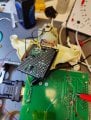
Working on recreating a tachometer board for a rarish car.
Car is a 4 cylinder and tach receives signal from negative side of the ignition coil.
The EMA for the mag needs 1.75v at 7,000 rpm (117hz)
Using circuit attached for values for capacitor.
6k resistor is actually two 12ks in parallel and the 100k resistor on vout is a trimmer pot
This circuit will receive input from the negative side of the coil, and of course I built the circuit then realized (after testing and frying my lm2917) that I must condition the input to be a cleaner square wave without any huge spikes.
Anyone have suggestions on the best method of approaching this?
Attachments
-
 77.4 KB Views: 30