analog circuit design - BJT amplifier

Thread Starter

Noam Dvir

Joined Jun 15, 2015
2
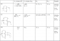
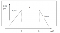
hello, i need to design analog circuit that has a transfer curve as seen in the following image using resistors, capacitors,voltage, and BJT (with beta value of 100).
the parameters are:
A=75
f1= 21Hz
f2=21 KHz
M1=40
M2=-20

the circuit also need to have input resistance of Rin= 60 kilo-ohm and output resistance of 51 kilo-ohm.

can anyone help me figure out how this type of circuit should look like?
 

Attachments

Kermit2

Joined Feb 5, 2010
4,162
YOU must make an attempt at designing the circuit.

After YOU do this, post the circuit here and we will help you correct any problems. We will NOT do it for you.
 

Thread Starter

Noam Dvir

Joined Jun 15, 2015
2
first of all, let me apologize if i gave the impression that i was trying to get you guys to do my homework for me. i most certainly wasn't (sorry I'm just pretty clueless at this point).

now for what i do know (or think I know):

i think the circuit should have 3 stages, each connected with a capacitor, where the first stage is for achieving the required input resistance, the second for the required gain, and the third is for the required output resistance.

(the first and last stages might also add some gain but it will be considered in the second stage)

My question is how do I know which of the following modules should I use for each stage?

Thank you!
 

Attachments

Veracohr

Joined Jan 3, 2011
772
My question is how do I know which of the following modules should I use for each stage?
Pick some resistor values then calculate the gain, Rin and Rout as outlined in your attachment. That should help you figure out which types are appropriate for which sections.

Are you sure your output resistance is supposed to be 51 kilo-ohms? That's rather high.
 
Top