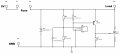
I thought it is better so the first protects upstream circuitry and the fuse from negative voltages.
And the second SK34 protects the load and sensitive devices downstream from negative voltages.
Or could this be problematic?.
I thought it is better so the first protects upstream circuitry and the fuse from negative voltages.
And the second SK34 protects the load and sensitive devices downstream from negative voltages.
Or could this be problematic?.
I have one final question regarding R3 resistor.
With being 10k, the TL431 cathode current is only 70uA at the trigger point. Doesn't the TL431 require a minimum of 1mA for stable regulation?, won't this cause unstable triggering or a failure to fire during an overvoltage, or?
Yes, good point.
I think my original circuit had 500Ω so don't how it got to 10k.
The data sheet minimum is 0.4mA not 1mA, so an R3 value of 1k or less should be sufficiently low for proper operation.
Still will only dissipate a very small power, and that only for the short period when the crowbar circuit operates.
A series string of seven or eight fifty amp silicon power diodes, forward biased across the power buss, should clamp the voltage at 5.6 volts, if eight diodes are used. It may be that only seven diodes will actually be required. They need to have adequate heat sinks, and adequate sized wire must be used. AND the power source will need a protective fuse rated above it's maximum current rating.
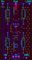
I finally finished the project and tested the PCBs, but it was a bit of a failure and I can't figure out what the issue is. Even with a 5V supply and no load connected, there is too much current draw. I believe the SCR is shorting power to ground, even though it is not suppose to trigger. I have tried several boards and they are all acting the same way.
I believe everything is in order, the strange thing I noticed is that when I tested with another power supply and I noticed it works fine as intended if the fuse was there (connected) before i turn it on. But if I left the fuse not connected and turned the power supply on then connected the fuse the SCR triggers!.
It may be the SCR is triggered by exceeding its dv/dt rating for voltage application at the anode.
The SCR internal junction capacitances can trigger it when a high dv/dt voltage is applied, and the sudden application of the supply voltage may do that.
Try adding a 10-100nF capacitor between its gate and ground.
Alternately, my sim shows the TL431 momentarily turning on and triggering the SCR when power is rapidly applied.
If my previous suggested capacitor addition doesn't help, try 0.5-1µF across the base-emitter resistor, R1.
The capacitor charging when you connect the powerpulls the "ref" voltage low until it is charged. THAT is what I suspect. So if you connect a second capacitor, the same as C1, in series with C1, to the positive power rail, that should reduce or eliminate the momentary voltage dip.
Often, START-UP conditions and responses, are different from steady state actions, and sometimes produce unintended results. IF you have already evaluated the suggestions in posts #30 and #31, and discovered that those are not the cause, then what else can it be??
Crutschow, I really appreciate your ongoing support and for sharing your expertise - it makes a huge difference.
The circuit is working perfectly now. Adding a 1uF capacitor across R1 stopped the random switching issues I was having. I did notice the SCR was latching automatically at power-up, but increasing the filter capacitor (C1) on the TL431 voltage divider from 1uF fixed that right up.

 Facebook
 Google
 GitHub
 Linkedin