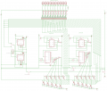
Your new schematic shows high power incandescent light bulbs on top of the truck but maybe they are LEDs that are missing current-limiting resistors. We must design the transistor circuit that can provide enough current. How much current for each light?
Ok here it is check the bottom and see if that is correct....
How would i control the ground with these circuits? just switch everything from positive to negative and visa versa? Or would i need a whole new set of components....?
Well, re-designing the flash controller to sink current would make the circuit a lot easier.
It would mean that you would have to supply your LEDs and incandescent lamps with 12v, and the control board would sink the current. This means re-wiring your LEDs.
Incandescent bulbs don't care about polarity. LEDs do; they won't work if they are connected backwards.
They are Walmart bought Blaze Amber Marker Lights. 6 Led's a piece and there are ten of them. I dont know how to figure out the current each one of these would need. How do i do that? and the package doesnt say...
Sorry they are not Incandescent lamps... I couldnt find anything that had 6 LED's in a bunch so i put that there to represent there were lights on top.
The package of LEDs will say what voltage. They might be made for cars and trucks so are designed for 12V.
You should never buy cheap ******* LEDs that have no spec's.
If they are designed for 12V then plug one into the cigarette lighter jack and measure its current with a multimeter.
They are pre-built lights for a truck or trailer, They are 12v and i will test them in an hour or so once i get home from class. They are 2x3 inch Amber Marker lights with 6 LED's in each ill check the current load once i get home.
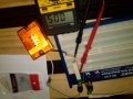
So i Have a 460ohm resistor that i put in between the 12v+ and the positive lead on the Light. The meter read 5.09DCV Which means there is a 7V drop across the resistor. So if i do OHM's Law i take 7/460=0.0152 so does that mean each Light(6 LED's) Draws .02 amps or 20uA per light?
You forgot to say how many LEDs lighted.
0.0152A is 15.2mA which would make a single ordinary small LED pretty bright. It would make six LEDs look dim with only 2.5mA each.
But without your very high value resistor (you are supposed to use 1 ohm or less) then the current will be much higher.
Don't forget that you will get a different reading when the engine is running at a fast idle vs engine off. This is because there will be more voltage available when the alternator is generating current output.
You've only shown some of the 4017 outputs used - is that how it is really wired?
Just trying to clarify things here.
By the way, what version of Eagle did you install?
So i Have a 460ohm resistor that i put in between the 12v+ and the positive lead on the Light. The meter read 5.09DCV Which means there is a 7V drop across the resistor. So if i do OHM's Law i take 7/460=0.0152 so does that mean each Light(6 LED's) Draws .02 amps or 20uA per light?
OK, you dropped a decimal point and rounded things off a bit much, and you're reading in the wrong place.
You need to read the drop across the actual resistor. The Vf of the diode (LED) will be somewhat constant over a wide range of current. However, the voltage across the resistor will directly correspond to the current flowing through it.
Therefore, you have to repeat the measurement, but take it across the resistor, not the LED or array of LEDs.
Besides, are you certain that's a 460 Ohm resistor? That is not a standard value. It is more likely to be a 430, 470, or 510 Ohm resistor.
A table of standard resistance values is here: http://www.logwell.com/tech/components/resistor_values.html
Bookmark that page.
Use the green columns, as E24 values are typically available from local shops. You usually have to special order E48 or higher values, and they are more expensive.
Don't forget that you will get a different reading when the engine is running at a fast idle vs engine off. This is because there will be more voltage available when the alternator is generating current output.
Yes i bought them from a friend... Ill get a 1 Ohm and let you know tomorrow i think i did it right just wrong resistor!
AudioGuru:
All of them lighted up just not as bright as they should of ill take a picture tomorrow and show you what im talking about. Its hard to explain...
 Facebook
 Google
 GitHub
 Linkedin