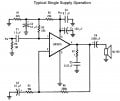
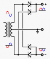
The schemathic that I uploaded earlier is maded for LM1875 but I heared that it works with tda 2030 too and now I don't know wich datasheet to work for.
And I need ti know the supply voltage
The problem that I'm worryed about is that now I don't know wich one of the data sheet to respect, tda 2030a or lm1875 datasheet, because the schematic that I uploaded is taked from lm1875 datasheet just that I replaced the lm1875 with tda 2030a.
I think it is obvious that if you use tda2030, you refer to the tda2030 suggested design in the tda2030 data sheet. If you use lm1875 you will use the design in the lm1875 data sheet.
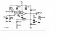
huf, I was in a time breakdown, now I have decided to use TDA2030A because I have bought this component, and I use this schemathic:
The problem that I want to ask is about the speaker, the speaker in the sch is just for example , i think, I will need to connect a loudspeaker used to pc, for example, I want to know what connector to use.
Also I want to know what connectors for supply voltage on my pcb to use. VCC, Ground, Etc, Thanks.
From what I saw on the providers sites on the internet are two tipes of conectors RCA and Jack conectors.
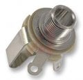
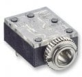
But and those are diferent, I have to choose this two variants:
1. and
2.
I'm still blocked at the PCb layout because I don't have any experience in making PCB's and I don't know how to proceed.
At the first variant I think that two wires conected to the connector would do the job
The second variant, I think that need a footprint, but I didn't find one
My problem is now the voltage transformer, in my datasheet specifications the Vs is +/- 22V, what kind of transformer I need? 230Vac to 22Vac or 230Vac to 22Vcc?
The absolute max allowed supply voltages for the TDA2030A is plus and minus 22VDC but it is spec'd with plus and minus 16VDC for an output of 12W into 8 ohms. They say that a max of plus and minus 18VDC provides good reliability.
A full-wave power supply uses a center-tapped transformer and a bridge rectifier. For plus and minus 18VDC when the mains is 10% high and the amplifier has no load then the loaded DC with a normal mains voltage is about 16.2VDC.
A transformer that has a 24V center-tapped winding produces a rectified and filtered plus and minus 16VDC. it will be about plus and minus 18VDC with no load and will be plus and minus 19.8V with the mains voltage 10% high and no load.
A stereo amplifier will have an output of 24W and heating of about 16W for a total of 40W.
A 24V/40W transformer has a rated current of 1.7A.
EDIT: i found a power supply schematic that does not show the main filter capacitors.
At the top of the page you posted it says, Vs= plus and minus 16V then further down it says the output is 12W into 8 ohms. The graph in figure 3 shows an output into 8 ohms of 12W when the supply is 32V and the distortion is fairly low.
It shows an output of 16W when the supply is plus and minus 19V.
I didn't find where they say that the plus minus 18VDC is recommended.
The datasheets of most similar amplifier ICs like the LM1875 shows heating of 8W per channel when the output is 12W per channel.
Since the output power and heating of the TDA2030A are so low then they don't show the heating on the datasheet.
Why for example plus minus 6V represents 32V? What represents this 32V and why is specified in that way in datasheet? In my opinion it isn't neither rms value, neither medium value, what represents that interval?
Why for example plus minus 6V represents 32V? What represents this 32V and why is specified in that way in datasheet? In my opinion it isn't neither rms value, neither medium value, what represents that interval?
I don't know what you are talking about. Maybe you are talking about the output power is rated on the datasheet when the distortion is 10%. Then the output of the amplifier is clipping badly and sounds awful but the output power number is about 25% higher than if the output is as high as it can go with low distortion (at clipping).

 Facebook
 Google
 GitHub
 Linkedin