 Facebook
 Google
 GitHub
 Linkedin
I am working on a project where i am amplifying a fire alarm signal using a microphone and an inverting amplifier. Instead of a dual supply of +/-12V I am trying to use 24V with a 12V reference to achieve +12V and -12V for my lm2902 op-amp Vcc and Vee respectively. I will post a photo of my schematic and of my circuit. My confusion is how to connect the Vcc and Vee to my capacitor circuit to get -12V.
Attachments
-
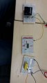 117.1 KB Views: 13
 -
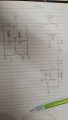 78.4 KB Views: 14


