Amp FAIL!

Thread Starter

Theory

Joined Nov 3, 2015
28
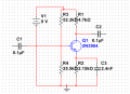
I have designed a class A amplifier ( its my assignment, note that im student). My problem is that the output ain't amplified instead it is smaller that the input. Whats the problem ? It is a Common Emitter btw.
 

Attachments

MikeML

Joined Oct 2, 2009
5,444
...There is. My simulator look that way, Sorry sir. its Voltage divider sir. A common emitter configuration :)
Since your simulator correctly put connection dots at the other nodes, I suspect there is no connection to the base of the transistor except the input coupling capacitor, hence no bias.

At what frequency? You need to use .AC analysis (not .DC) and determine the gain vs. frequency (Bode Plot).[/user]
 
Last edited:

Thread Starter

Theory

Joined Nov 3, 2015
28
Sirs? What if im going to make this a 2 stage. Can i just attached same amp to it with a cap between them ? And btw thanks it works now. :D
 

Attachments

#12

Joined Nov 30, 2010
18,224
Yebbut...you might want to place about a nanofarad in parallel with R1 to limit the gain above 30KHz.
 

Thread Starter

Theory

Joined Nov 3, 2015
28
What type of cap are being used in amplifiers? Some schematics have non-electrolytic, and some are using electrolytic. Can someone clarify this?
 

Jony130

Joined Feb 17, 2009
5,487
It will depend on the capacitor value. If C is > 1μF we are going to use electrolytic capacitor. But if C < 1μF we can easily use non-electrolytic cap for example a metal film capacitors. And in general we are trying to avoid the ceramic capacitors in the signal path unless the cap is < 1nF and we are gonna to use Class 1 ceramic capacitors.

As for your amp:

C1 > 0.16/(300Hz * R3||R4||(hfe+1)*26mV/Ic) ≈ 0.16/(300Hz * 3kΩ) = 177nF, so we need to use 220nF.
C3 > 0.16/(300Hz * 26mV/Ic) = 0.16/(300Hz * 26Ω) = 22μF
C2 > 0.16/(300Hz * (R1 + Rload))
 

#12

Joined Nov 30, 2010
18,224
I handed you the answer (and now I regret doing that). What kind of component, where to place it, and a fair estimate of the size. This being the Homework Forum, why don't you use the formula that you already know (post #12) and find out if using only R1 results in about a nanofarad of capacitance being the right size? Is it easier to ask 6 times over the course of 4 days than to do one line of math?
 

Thread Starter

Theory

Joined Nov 3, 2015
28
I actually did it sir, @#12 . I just asked for clarifications since i learned that inorder to control my highest freq, all i need to do is put a capacitor in parallel with Vce( goin to ground) . That's why doubts are coming.
 
Top