 Facebook
 Google
 GitHub
 Linkedin
Hi guys,
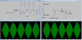
I'm looking to make a very bobby basic envelope detector out of a diode and RC network. I modelled two circuits with different schotty diodes and got very different waveforms (see attached). One matched the input envelope well but had some high frequency noise on the output. the other was smoother but had a very slow decay on the falling edge.
I would rather have the former but I don't know what diode characteristics to be aware of when selecting. I thought it might have been the capacitance when reversed biased but for two of models I used that had slow decays, one had a larger capacitance and one had a lower capacitance than the MBRS340 that I used in the "good" model.
I want to have as low a forward votlage as possible as my signal is quite small.
Does anyone have any insights they can share with me?
Attachments
-
 145.2 KB Views: 89


