Facebook
 Google
 GitHub
 Linkedin
Hello All;
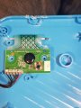
I am working to modify a LeapFrog toy which is a book with buttons and a speaker. It is this model.
The buttons on the book pages is actually a sheet of a membrane with a ribbon cable popping out the back to a main board. The issue I am running into is addressing these buttons. The 9 buttons go into a black chip-on-board and produce only 6 pins which feed into the main board. Image here: https://imgur.com/a/dJSquWq
I assume this chip is to help provide additional voltage for the ribbon cable to run the extra length. However, does anyone know if there is there a way arduino can use these 6 pins to address the buttons, and how would I go about identifying how these work?
Any help is greatly appreciated!