Airsoft MOSFET Burning out

Status
Not open for further replies.

Thread Starter

Alcodast

Joined Aug 29, 2016
9
I build little MOSFET systems for Airsoft guns to save the trigger from arching and decrease overall resistance. I having the issue of the FETs getting really hot as the replica is fired, until it finally locks closed and burns itself out.

http://unconventional-airsoft.com/wp-content/uploads/2009/08/Simple-MOSFET-Setup-2009-06-22.jpg


I have been building these little trigger chips for some time now, but one particular gun is giving me some trouble. I have tried five different versions of the circuit, making slight variations to the resistors and solder arrangements.
The gun houses an m120 spring on a standard gear ratio with a stock motor, which means that there is a smallish ferrous motor pulling an 8 inch 80lb spring. The system draws about 35A sustained with an initial spike somewhere around 350A, and the battery can safely put out 65A sustained.

I've been dealing with this problem for far too long and am coming to this community in an effort to avoid spending $40 on a commercial Airsoft trigger controller. Please help me figure out why my FETs are burning out.

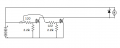
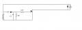
Super simple system. I'm not very familiar with schematics, so some of this may be off, but I am following the basic idea of the video linked above. The Diode is 18V, placed to absorb voltage spikes.

Design1.png
 

#12

Joined Nov 30, 2010
18,224
Lots of questions here...or maybe it's just ignorance.
What kind of battery are you using to get a 350 amp start surge?
Do you actually believe you can get 350 amps through those tiny legs on the mosfet?
And the motor..a 385 watt DC motor? How much does it weigh?
ps, I can't find that mosfet part number. IRLB3034
Do you have a different part number or a link to a datasheet?

Note to helpers: That 12 minute video is mostly a soldering lesson. The schematic is more helpful except the diode is a zener with the wrong symbol.
 

Thread Starter

Alcodast

Joined Aug 29, 2016
9
The battery is an 11.1V 2200mAh 30C LiPo hobby battery. The surge measurement is an estimate based on a computerized multimeter a friend of mine has.
The Motor is not 385 Watts... It's one from this company ( http://www.chaolimotor.com/EN/product.asp ), pictured foremost in the banner, but I cannot find it in the catalog. It is the standard stock Airsoft motor you find in most china-made replicas.

Here is the data sheet.
http://www.infineon.com/dgdl/irlb3034pbf.pdf?fileId=5546d462533600a40153566027b22585

Design1.png
Updated the schematic a bit. Still learning here.

http://www.airsoftguns.ie/2857-thickbox/ad-classic-aeg-standard-motor-long.jpg
 

#12

Joined Nov 30, 2010
18,224
You started with a pretty good mosfet. The one I found is only a tiny bit better.
I would place a Shottky diode across the motor so the inductive kick goes back into the positive power wire instead of trying to bypass it around the mosfet with a zener diode. Less power wasted in the diode means less heat by about 2/3rds. 200 watts peak instead of 630 watts peak.

ps, your diode is upside down in post #3

Another idea is to bolt the mosfet to a piece of metal to cool it down instead of wrapping it in an insulator to keep it hot.

And, finally, you can keep the zener diode in to protect the mosfet, but I don't think the inductive kick is going to jack the battery voltage up above the 24 volts required to destroy the mosfet.
 
Last edited:

Thread Starter

Alcodast

Joined Aug 29, 2016
9
Concerning amperage, I know for a fact that the gun pulls a sustained 2A-35A draw depending on the position of the gears. I also know that the Battery can safely put out a maximum of 65A for an extended time, though the charge will not last long in that situation. This is a very powerful gun, hence the need for the MOSFET in the first place. Without it, we get major arc burns, rendering the trigger switch useless after only a couple dozen pulls.


Why would power in the diode make the FET get hot? And What is causing my circuit to fry?

Can you describe the different types of diodes for me? I know they block current in one direction, and zenners let it go if the voltage is high enough, but not much else about their properties.

Why is that MOSFET better than the 3034?

Won't pass the 24V threshold: Even considering the volatility of Lithium Polymer batteries?

And finally, assuming my numbers are correct, what do I need to do to make the system work?

I ask all this out of ignorance. Feel free to talk down to me. I'm but a young chap dabbling in the dark arts...
 

#12

Joined Nov 30, 2010
18,224
Why would power in the diode make the FET get hot?
Because you connected the zener diode directly to the mosfet, then wrapped them in an insulator, according to the movie.
And What is causing my circuit to fry?
The mosfet is getting too hot.
Why is that MOSFET better than the 3034?
1.2 milliohms instead of 1.4 milliohms
Can you describe the different types of diodes for me?
The Shottky diode has a lower forward voltage than a standard rectifier with the same ratings. At 35 amps, about 6 volts for the one I named.
I believe you can get a better one. A rating of 5 amps would be even more efficient than the 3 amp Shottky I named.
Some big rectifier diodes might be just as good as the Shottky at 35 amps, but they will be larger.
The zener has 18 volts across it when the 35 amps hits it.
18 volts...6 volts...same current...which one gets hotter?
Won't pass the 24V threshold: Even considering the volatility of Lithium Polymer batteries?
The battery isn't going to increase its own voltage when you shut off the motor. The current through the motor has to go somewhere when you shut off the mosfet, so I told it to circle around to the positive end of the motor and keep doing that circle until the energy is used up instead of jumping through the zener diode and heating the zener. Theoretically, 11.1 volts plus 6 volts = 17.1 volts at the top of the mosfet during shut-down. It takes 24 volts to pop that mosfet, so it should be safe unless you flinch on the trigger and try to shut off the mosfet with a hundred amps flowing through the motor. In that case, the zener would be a backup safety feature, but I'm not sure the zener can take a hundred amp hit and stay at 18 volts. I would have to do some measurements to see if you're really blowing 350 amps through that motor and what the zener is going to do when that much current hits it.
assuming my numbers are correct, what do I need to do to make the system work?
I thought I just told you. Optimize the parts, get the zener heat away from the mosfet, and use a heat sink instead of an insulator.
If that isn't good enough, use 2 mosfets in parallel.
For the moment, stick with your 40 volt mosfets and see if the other suggestions are enough to fix the problem.
 

Attachments

Last edited:

Thread Starter

Alcodast

Joined Aug 29, 2016
9
Would having parallel mosfets split the current/heat?

It is not a good idea to have the conductive parts exposed during play, so I put on shrink wrap to protect the chip. Is there a safer way to go about protecting the chip while still providing adequate cooling?
 

#12

Joined Nov 30, 2010
18,224
Would having parallel mosfets split the current/heat?
Why else would I suggest two transistors for an overheating problem?
Is there a safer way to go about protecting the chip while still providing adequate cooling?
Don't mount it where it can short to metal parts.

I've never seen an airsoft gun. Are they made of metal?

Use an insulator kit to mount the transistors to a piece of metal so the metal isn't connected to power in any way.
 
Last edited:

#12

Joined Nov 30, 2010
18,224
Here's another way to look at it. Two wires from the motor to the mosfets will help balance the current because the wires have a little bit of resistance in them.

ps, I did finally find a reference that tells me the LiPo battery can supply 66 amps.

pss, It's bedtime. 2 am and I'm tired.
signing out for tonight.
 

Attachments

Last edited:

Alec_t

Joined Sep 17, 2013
14,280
it should be safe unless you flinch on the trigger and try to shut off the mosfet with a hundred amps flowing through the motor.
Perhaps contact bounce in the switch is causing that effect to happen; hence the FET frying.
 

#12

Joined Nov 30, 2010
18,224
Perhaps contact bounce in the switch is causing that effect to happen; hence the FET frying.
That's an idea. I woke up today thinking about a diode from the trigger and a capacitor to guarantee a minimum hold time but that puts a, "slow" on the gate and I don't quite know what to do with that. How slow can you ramp down a mosfet that is hauling at least 35 amps?
Here's a drawing. If you can name C1 and R1 we can work with that.
Then there is the possibility of really complicating this with a one-shot pulse generator. That would get a debounce and a fast turn off.
 

Attachments

Alec_t

Joined Sep 17, 2013
14,280
I share your concern about slowing the gate charge/discharge, which C1 would definitely do :(. The answer might be a monostable (which is probably more complex than the TS would like) to give a sharp on/off.
 

Thread Starter

Alcodast

Joined Aug 29, 2016
9
http://m.ebay.com/itm/321057005593?_mwBanner=1

here is the type of switch it has. It would make perfect sense that there would be contact bonce, as there is an arm in there that clicks back and forth between circuits.

what if you used a cap and a zenner so there would be a slight delay on throwing the switch. Can you make it so there is a variance in voltage so there is no complete circuit until it reaches, say, 7V, by which time the trigger has stopped bouncing?

I or can I add in a different kind of IC to create a slight delay to give time for the switch to close all the way?

What would it look like with a monostable? Can't I get that as an IC, then just plug and chug?

I'm looking for ways to swap out the clicker switch, or to make it bounce less but have come up empty so far. The problem is that the gearbox mounting for the switch is specifically designed to fit this switch, so there is not much flexibility. I do have access to a 3D printer. I'm going to look into building a custom switch to house a microswitch button.
 

#12

Joined Nov 30, 2010
18,224
Can you make it so there is a variance in voltage so there is no complete circuit until it reaches, say, 7V, by which time the trigger has stopped bouncing?
You have a bad mental model of switch bounce. What it looks like is a bunch of zero to max pulses that span a few milliseconds. There ain't no slow ramp. It's a wad of trash looking thing on a 'scope.

The mosfet has a capacitance in the gate and you started out with 100 ohms to put a charge time constant on that. I calculated it to about 0.6 microseconds yesterday which is insignificant compared to switch bounce time. Bounce time is about 10,000 times that long. The main problem with a simple slowing circuit is that the mosfet will heat terribly if you take several milliseconds to start it up and several milliseconds to shut it off. I think the ultimate cure is a 555 timer chip set up as a non-retriggerable one-shot (monostable) so the chip catches the first bounce and fires the mosfet for x number of milliseconds, then shuts off hard and refuses to accept a reset from the trigger until you release it. That x number of milliseconds would be the amount of time for a full cycle of the motor.

The next level would be a 556 timer with one section doing the debounce and the other section cycling the airsoft gun into full automatic. I don't think you want that...or do you? Right now, we're talking about a new design that is probably marketable. Idiot proof trigger with single shot or full automatic like a true assault rifle. Does an airsoft come with a 30 round clip?

For now, try the obvious changes. Use a Shottky diode on the motor to take the load off the zener and try to cool the mosfet instead of insulating it.
 

Thread Starter

Alcodast

Joined Aug 29, 2016
9
Okay I'll make it and see how it performs.

Do you think you can make a diagram of how to integrate the 555 into the design. I can figure out values for timing later, but I want to get an idea of how that would be assembled.

Unfortunately, all airsoft guns have different gear timing and rates of fire, so having a shot control system based on timing would not be effective. Fortunately, however, there are many chips on the market that have effective methods of fire control, though they are very expensive.
 

ronsoy2

Joined Sep 25, 2013
71
Did you determine yet if it is heat blowing the FET? Calcs show that the FET should easily handle 40 amps without getting overly hot. You could be having gate fail taking out the FET. Try a 12 volt 1 watt zener diode from the gate to source to stop any RF spikes that are coming from the motor. All the stuff about contact bounce and 555's and other oddball stuff is hokey poke. First determine if heat is really the culprit. I'm betting on gate fail from RF spikes.
 

Thread Starter

Alcodast

Joined Aug 29, 2016
9
Yes it can handle 40 amps no problem. The trouble is that its having trouble when the gate voltage is coming and going during the spike to get the motor going, when it is taking 100-200 amps. Knowing what I know about the parts involved, this makes perfect sense.
 
Status
Not open for further replies.
Top