Airline coffee maker for home tiki bar

Thread Starter

nearbeer2001

Joined Aug 12, 2021
4
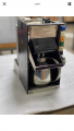
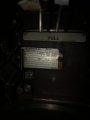
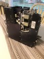
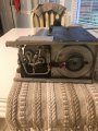
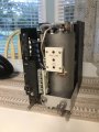
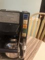
I have a airline coffee maker that I would like to resurrect and make part of my future home tiki bar area. It is powered by 115v ac three phase 400 hz.

I no background in electronics or power engineering but I am pretty good at splicing wires, soldering, and terminating wires.

A co-worker stated that it may be possible to use a Variable Frequency Drive to power the coffee maker but he wasn’t 100% positive.

What are your thoughts on how to run this coffee maker operate on household 115v single phase 60hz?

In search of my next cold one,
NearBeer
 

Lo_volt

Joined Apr 3, 2014
317
There are devices that will convert the frequency, but they're a bit pricey for use with a coffee maker.

Can you find a make and model number on the unit? We can try to find out what's in it. It's possible that it might work on 60Hz without any modification.

Is is an automatic drip unit or does it have a motorized pump inside?
 

LowQCab

Joined Nov 6, 2012
4,072
It depends on what Voltage it is designed to run on.
Does it actually have 3-Power Wires and a Ground-Wire ?
Or just 2-wires, and a Ground-Wire ?

If it has only 2-Wires, it could be 115-Volts, or, somewhere around ~208-Volts.

Depending on how it's built, You may be able to simply parallel
all 3-Heating-Elements, then replace the Power-Cord with a
larger gauge, replacement Appliance-Power-Cord, and be good to go.
.
.
.
.
.
.
 

MrSalts

Joined Apr 2, 2020
2,767
I don't know how someone could imagine that a 3-wire / three phase 115v appliance could somehow jump to 208v when only two wires are connected - life and physics don't work that way.

The project depends on what is included in your coffeemaker. How complex is your system?
- Two wire or three wire (plus ground if any (doubtful)).
- any on-board electronics (timers and or displays or LEDs or ...?).

let us know what you find.
 

LowQCab

Joined Nov 6, 2012
4,072
I don't know how someone could imagine that a 3-wire / three phase 115v appliance could somehow jump to 208v when only two wires are connected - life and physics don't work that way.

The project depends on what is included in your coffeemaker. How complex is your system?
- Two wire or three wire (plus ground if any (doubtful)).
- any on-board electronics (timers and or displays or LEDs or ...?).

let us know what you find.
You need to re-read my post.
 

LowQCab

Joined Nov 6, 2012
4,072
Damn, that thing pulls HUGE Power.

Assuming that You could parallel the Elements,
that would add up to ~27-Amps at 120-Volts.
And, You probably can't run it on 240-Volts
without the risk of too much Heat causing one of the elements to burn-out,
because the Voltage difference between Phases in
a 3-Phase-System would be around ~208-Volts.

To Power this thing,
You will have to install a special Circuit from your Breaker-Panel.
.
.
.
 

MrSalts

Joined Apr 2, 2020
2,767
Damn, that thing pulls HUGE Power.

Assuming that You could parallel the Elements,
that would add up to ~27-Amps at 120-Volts.
And, You probably can't run it on 240-Voltsh
without the risk of too much Heat causing one of the elements to burn-out,
because the Voltage difference between Phases in
a 3-Phase-System would be around ~208-Volts.

To Power this thing,
You will have to install a special Circuit from your Breaker-Panel.
.
.
.
Really, a "special circuit" in the breaker panel? How do you get three phase 120 from a split phase 240 residential feed?What does this special circuit do to convert split phase 240 to three phase 120vAC?
 
Last edited:

LowQCab

Joined Nov 6, 2012
4,072
My comment was based on the idea of simply tying all 3-Phase-Wires together,
this would create a Single-Phase-Load.
The Spec-Plate says, 3-Phase, 9-Amps per Phase.

A Coffee-Maker consists of Heating-Elements,
and maybe a few other very Low-Current Loads.
This is not a Motor, and there's no 3-Phase Transformer involved,
therefore, all 3-Phases may be connected together
as a single Load, after the Thermostat Circuitry has been
verified, and modified if necessary.

This means that with an expected 3-Phase Load of ~9-Amps per Phase,
when all 3-Phases are connected in parallel,
the Current will increase to ~27-Amps at ~120-Volts.
That equates to a minimum of a ~30-Amp, 120-Volt Branch Circuit.
This requires a minimum of 10-gauge-Wire, and a 30-Amp Circuit-Breaker.

30-Amp Residential-Branch-Circuits are extremely rare and unusual,
and are generally custom installed for a special dedicated Load of some sort.

Normal Residential-Branch-Circuits are rated at 15-Amps max,
and are only intended for use at a maximum of 80% of that 15-Amps.
1 or 2 Kitchen, or Bathroom Circuits may be rated for 20-Amps in some cases.
.
.
.
 

LesJones

Joined Jan 8, 2017
4,190
Re post #10. I imagine 115 volts is the phase to phase voltage rating. So considering it as three elements wired in star configuration (Even though there is probably no connection to the star point which would be neutral. ) then the voltage across each element will be 115 divided by root 3 which gives about 66 volts. so the total wattage will be 3 x 66 x 9 = 1782 watts. (NOT 3 x 115 x 9 = 3105 watts.) If the elements are wired in star mode then it can't be used without a transformer as 66 volts would be required if the elements were connected in parallel. If the elements are originally connected in delta configuration they could be re connected in parallel with 115 volts across them, the total current would be 1782 /115 = 15.5 amps. (Not 27 amps.).

Les.
 

Lo_volt

Joined Apr 3, 2014
317
Given LesJones's input, which is it, phase to neutral or phase to phase? The wording on the spec plate makes me lean toward each one being phase to neutral.
 
Last edited:

Lo_volt

Joined Apr 3, 2014
317
I don’t think it has a pump
I think you're right. That's a good thing as a 400 Hz motor won't run quite right on 60 Hz.

I think LowQCab is leading you in the right direction. It does look like there are 3 heaters, one on each of the 3 phases. If he's correct that each one draws 9 amps, that might be a problem. That's a lot of current to draw through a normal 120 volt outlet.

I'm trying to think of a way of checking the heaters to see what voltage they are rated for. You could power them up in series at 120 volts and see how hot they get and how fast they heat up. If you do power them up, make sure you have water in the system. Typically water heater elements don't like running dry. You will ruin them if you power them up dry.

Does anyone have a better suggestion?
 

Reloadron

Joined Jan 15, 2015
7,517
Well the name plate certainly cleared things up. With the heating elements aside I have no idea what any internal electronics may look like. While heating elements likely won't care about line frequency the rest of the guts might. Anyway yes, you could likely use a phase / frequency converter but looking at the load that is considerable current to be considered. Unless you want this as a novelty I am not sure I would pursue the project. Then too if nothing else is affected you can as mentioned parallel the elements and take into consideration the need for a heavier gauge wire to power the creature. Where the elements tie together you want likely AWG 10 as a minimum.

Ron
 

LesJones

Joined Jan 8, 2017
4,190
I think measuring the resistance of one of the elements (With at least one of it's wires disconnected.) is an easy way to work out which interpretation of the 115 volts is correct. While doing this you could also check if they were wired in star or delta configuration. One other possible problem is if the solenoid valves are AC then they would probably overheat as their reactance at 60 hz would be lower than it is at 400 hz. If there are any transformers in the unit they would burn out when run on 60 hz.

Les.
 

Reloadron

Joined Jan 15, 2015
7,517
I think measuring the resistance of one of the elements (With at least one of it's wires disconnected.) is an easy way to work out which interpretation of the 115 volts is correct. While doing this you could also check if they were wired in star or delta configuration. One other possible problem is if the solenoid valves are AC then they would probably overheat as their reactance at 60 hz would be lower than it is at 400 hz. If there are any transformers in the unit they would burn out when run on 60 hz.

Les.
That's another good point worth considering. There are solenoid valves in the images posted.

Ron
 

MrSalts

Joined Apr 2, 2020
2,767
Explore about disemboweling it and installing inside an available coffee maker guts on plain 120VAC, perhaps from Goodwill stores ? ( Assuming you care only to keep the airliner looks of it )
Hardly worth searching for a used one when a basic new coffee maker is $20. But I completely agree on the retrofit
 
Top