 Facebook
 Google
 GitHub
 Linkedin
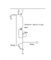
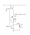
Ok, let me give it some thought, and I'll get back to youYup, adjust both slopes, and adjust the delay of the second led's slope kicking in
Again LED dimming and fading on
- Thread starter Chillum
- Start date


| Thread starter | Similar threads | Forum | Replies | Date |
|---|---|---|---|---|
| D | hi from me again. questions about repairing nowadays at all ? | Jobs & Career Advising | 1 | |
|
|
again with the constant current generator | PCB Layout , EDA & Simulations | 9 | |
|
|
555 question again | General Electronics Chat | 5 | |
|
|
What's Old Is New Again | General Electronics Chat | 2 | |
|
|
AudioGuru Again | Off-Topic | 24 |


