AFX Slot Car Voltage Regulator for Lights

Thread Starter

Zorac

Joined Oct 9, 2016
23
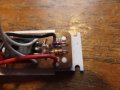
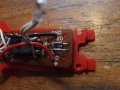
I have a slot car that has a voltage regulator (see attached diagram/pictures) for the lights and I am struggling with the diodes. The regular diode went (the diodes seem to expire on these boards) and i replaced with a small schottky (SR160) i had on hand (which was still too big than needed but fit under the cover). I was wondering if someone could help me out to spec the two diodes? the resistor in the diagram is a 1.5kohm @5%. While i recognize the circuit as a voltage regulator I don't really understand what it is doing. the zener has a 6 on it (or maybe its a 5 if you look at it just right).

A second question, I have a number of cars that have a single light that I would like to convert to LED that have the same large input voltage range (5v to 24v). i was thinking i could use a small regulator like a 79L05 to give me a constant 5v then use a 3mm led. this should still be a fairly light package (weight wise) and draw less current than the tradition bulbs the manufacture puts in the car. I would use two resistors, one to limit the voltage to the regulator (as it specs out at a max of 20v) and a second resister to put inline with the LED. 100ohm 1/4w should work in both cases. Would this work?

the car with the regulator in it is extremely slow so I may look at replacing the regulator they have with something small and LED to make the car faster and a bit more competitive.

any ideas would be great, thanks!
 

Attachments

Thread Starter

Zorac

Joined Oct 9, 2016
23
no idea what the draw is but there is no heat sync so it cant be much. measuring 'I' would be easy enough, but 'ILoad' would be hard (would need to remove components from the board). the load is 3 tiny (roughly a 3mm diameter) incandescent bulbs. here is an example:

http://www.slotcarsdirect.com/images/AFX8816.JPG

i have an extra diode, is that so current doesn't go backwards through the circuit which would essentially be braking on the car?
 

Thread Starter

Zorac

Joined Oct 9, 2016
23
So, I read your link a few times to try and understand it a bit better and realized I needed more measurements. At a full 24v 'I' measured 146mA, with nothing connected (although everything still on the board) RLoad = 4.2ohms (I figured this should be reasonably close as the transistor is like a switch so that should be the resistance of the load only?) which means ILoad should be 0.9A.

After a bunch of youtube videos on voltage regulation with a zener I then had an oops moment. Forgetting to switch my volt meter from current to to voltage (i was going to measure the voltage drop over the resistor) i cooked the transistor which leads me to a new set of questions (and a long waiting time for a new d882p to arrive)

1. The plain diode is actually there to protect the zener otherwise it would be trying to regulate the power over the car's motor. Given the draw of 146mA something like a 1N4148 diode should work? (rated at 150mA nominal, 500mA max).
2. The zener provides the reference voltage for the Vout, don't I just take my desired Vout + 0.6 for my zenner voltage? in this case a 3.9v zener rated for 0.5watts should be fine?

The third question (see attachment) is for my single light slot car (only the cars with 3 lights have the voltage regulator circuits).
3. would the attached circuit work? Although Vin is 24v, I would expect the car's motor would create a voltage drop and the 100ohm resistor up front should be enough to get it down to the 20v maximum for the 79L05.
 

Attachments

Thread Starter

Zorac

Joined Oct 9, 2016
23
a few more pictures from someone else also looking for replacement parts. a bit clearer than mine were. if I'm reading the markings right it looks like the diode is a 1N41 variety (by the stripes on one of the cars, the other has a PH marking but I can't find a reference to that) and the zener looks to be a 3.6v with a max If of 200mA. so what i proposed above should work.
 

Attachments

danadak

Joined Mar 10, 2018
4,057
1. The plain diode is actually there to protect the zener otherwise it would be trying to regulate the power over the car's motor. Given the draw of 146mA something like a 1N4148 diode should work? (rated at 150mA nominal, 500mA max).
1n4148 should be OK at 200 mA at nominal temperature. Normally one does
a simple thermal analysis to make sure Tj not exceeded. But this case looks
OK.


2. The zener provides the reference voltage for the Vout, don't I just take my desired Vout + 0.6 for my zenner voltage? in this case a 3.9v zener rated for 0.5watts should be fine?
Vout = Vz + Vbe, or Vz = Vout - Vbe


The third question (see attachment) is for my single light slot car (only the cars with 3 lights have the voltage regulator circuits).
3. would the attached circuit work?
Problem with this is transients, motor speed changes due to loading vs its current draw.
You would be better off with a reg that supports max Vin or a zener whose V drop does not
change significantly with current thru it over its normal operating range.


Regards, Dana.
 
Last edited:

Thread Starter

Zorac

Joined Oct 9, 2016
23
Vout = Vz + Vbe, or Vz = Vout - Vbe
I think that's what I've done? Took a bit to realize what Vbe was when I was going over it yesterday... :)

Problem with this is transients, motor speed changes due to loading vs its current draw.
You would be better off with a reg that supports max Vin or a zener whose V drop does not
change significantly with current thru it over its normal operating range.
you mean the 79L05 won't respond fast enough and some of the transients will go through it? this still has to be better than just running a 1k ohm resistor and a diode (which some do, but I find the LEDs dont last long as my track voltage is a bit higher than some, the LED isn't a constant brightness and it doesn't come on until the car is moving pretty good). when you say a zener reg you mean running just a current limiting resistor (1k or probably a bit smaller) and a zener (Vz=2.0v to match the LED forward voltage?)to control the voltage, wouldn't I need a diode as well so I didn't drop the voltage on the motor or is the limit amount of current that would go through the resistor not worth stopping?

http://www.reuk.co.uk/OtherImages/zener-diode-voltage-regulator.gif
 

danadak

Joined Mar 10, 2018
4,057
Its the input transients that overstress the part. And those can hose the part in
< 1 uS or so.

Series zener, just a known fixed V drop in series with reg input. No R needed.
So Power > zener > reg input is connection.

You want LED current to be constant in order to get fixed brightness, normally preferred
way is to drive with a current source. But a series R to LED "effects" a current
source of sorts. Especially when that series R is being fed with a known V. In
high power LEDs, where currents are high, series R not good solution, then
you should build a current source that makes immune LED V vs T variations.

Regards, Dana.
 
Last edited:

Thread Starter

Zorac

Joined Oct 9, 2016
23
just a follow up if anyone should need the info as well (took a while to get parts from aliexpress). while waiting for the parts i also bought another car that had the light board working correctly (needed a matching set of the cars anyway so neither racer has an advantage), it seems my board has some other issues as the output voltage was not correct on it as either. with a Vin of 8.45v the new board had an output of 5.8v. So on my old board I replaced the old standard diode with a 1N4148 diode, the zener with a 0.5watt zener with a Vz of 6.8, and replaced the transistor with the same D882. with the same Vin I get a Vout of 5.7v which is pretty close to my other car. might play with putting LEDs later, but I'll probably wait until a bulb burns out before I do that. the drop is a bit more than the 0.6v theoretical, not sure why, but its working well.

im only testing with a 9v battery for now, the track gets put away for the summer, but it will be brought back out when the weather turns cold for a through testing. :)
 

Dodgydave

Joined Jun 22, 2012
11,307
I would use a Lm7805 regulator with a 1N4148 diode in the Ground leg, this would give you approx 5.7V output @1 Amp max with an heatsink.


6V2-linear-voltage-regulator-circuit-schematic-diagram.gif
 
Last edited:
Top