 Facebook
 Google
 GitHub
 Linkedin
Hi,
I have a problem getting SPI communication to work right on the ADXL375z breakout board: Sensor seems to communicate, but only delivers nonsense-values. Examples:
- When registers are written at setup, they all show an eqal, wrong value (most of the time 0xE2 or 0x03. Mostly 0x00 after board reset.)
- Sensor values show 0x00, with occastional jumps to random value (independent of accelleration)
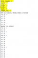
See attachted Screenshot of serial trace of register readback and values (registers marked yellow).
Some more facts:
- Sparkfun ESP32 board with Arduino (using ESP32 SPI Lib)
- Electrical connection/soldering verified --> is OK. VCC and VIO are OK.
- Tried a second ADXL375z --> same problems occur (the first one showed weired SPI signals on the oscilloscope, so I thought it might be damaged and bought a second one).
- SPI frequency is 2 MHz
- Exact same setup (wiring and code) works perfectly with an ADXL345 connected!
Is there anything special, maybe in addition to what is listed in the datasheet, that causes this problem?
I am thankful for any hints or tips for further investigation!
The SPI setup code on Arduino looks like this:
Moderator edit: added code tags
I have a problem getting SPI communication to work right on the ADXL375z breakout board: Sensor seems to communicate, but only delivers nonsense-values. Examples:
- When registers are written at setup, they all show an eqal, wrong value (most of the time 0xE2 or 0x03. Mostly 0x00 after board reset.)
- Sensor values show 0x00, with occastional jumps to random value (independent of accelleration)
See attachted Screenshot of serial trace of register readback and values (registers marked yellow).
Some more facts:
- Sparkfun ESP32 board with Arduino (using ESP32 SPI Lib)
- Electrical connection/soldering verified --> is OK. VCC and VIO are OK.
- Tried a second ADXL375z --> same problems occur (the first one showed weired SPI signals on the oscilloscope, so I thought it might be damaged and bought a second one).
- SPI frequency is 2 MHz
- Exact same setup (wiring and code) works perfectly with an ADXL345 connected!
Is there anything special, maybe in addition to what is listed in the datasheet, that causes this problem?
I am thankful for any hints or tips for further investigation!
The SPI setup code on Arduino looks like this:
Code:
void start_SPI_Measurement () {
delay(500);
digitalWrite(CS, HIGH); //Before communication starts, the Chip Select pin needs to be set high (disable).
delay(10);
pinMode(CS, OUTPUT); //Set up the SPI Chip Select pin to be an output from the Arduino.
delay(500);
//Initiate an SPI communication instance.
SPI.begin();
//Configure the SPI connection for the ADXL345.
SPI.beginTransaction(SPISettings(i_SPI_freq, MSBFIRST, SPI_MODE3));
delay(100);
// pullup CS am Sender ca. 5-10K (Kein Low außer aktiv runter gezogen)
// delays nach jedem write, gemäß Spec
// daten mind. 5 ns vor Clock-Wechsel anliegend Config SPI lib
// Set data-format
writeRegister(0x31, 0x0B); // #00001011 // volatile char DATA_FORMAT = 0x31;
delay(10);
writeRegister(0x2C, SAMPLE_RATE ); // Sample-rate of sensor i_sample_rate // 1600 = 0x0E im Code gesetzt wegen Arduino
delay(10);
writeRegister(0x1E, 0); // i_x_offset
delay(10);
writeRegister(0x1f, 0); // i_y_offset
delay(10);
writeRegister(0x20, 0); // i_z_offset
delay(100);
//Put the ADXL3x5 into Measurement Mode by writing 0x08 to the POWER_CTL register 0x2D
writeRegister(0x2D, 0x08); //Measurement mode
delay(100);
#ifdef DEBUG
// Readback registers for test
readRegister(0x31, 1, values);
Serial.print("DATA_FORMAT: ");
Serial.println(int(values[0]), HEX);
//Serial.print(" ");
delay(1);
readRegister(0x2c, 1, values);
Serial.print("0x2C: ");
Serial.println(int(values[0]), HEX);
delay(1);
readRegister(0x1e, 1, values);
Serial.print("0x1E: ");
Serial.println(int(values[0]), HEX);
delay(1);
readRegister(0x1f, 1, values);
Serial.print("0x1F: ");
Serial.println(int(values[0]), HEX);
delay(1);
readRegister(0x20, 1, values);
Serial.print("0x20: ");
Serial.println(int(values[0]), HEX);
delay(1);
readRegister(0x2D, 1, values);
Serial.print("POWER_CTL: ");
Serial.println(int(values[0]), HEX);
delay(1);
#endif
// Code for timer interrupt
/* Use 2st timer of 4 */
/* 1 tick take 1/(80MHZ/80) = 1us so we set divider 80 and count up */
timer_s = timerBegin(2, 80, true);
/* Attach onTimer function to our timer */
timerAttachInterrupt(timer_s, &onTimer, true);
/* Set alarm to call onTimer function every second 1 tick is 1us
=> 1 second is 1000000us */
/* Repeat the alarm (third parameter) */
timerAlarmWrite(timer_s, TIMER_INTERVAL, true); //initial 625 us = 1600 Hz sample rate
/* Start an alarm */
timerAlarmEnable(timer_s);
#ifdef DEBUG
Serial.println("SPI initiated, Measurement started");
#endif
}
// ************************************
// *** Utilities
// ************************************
//This function will write a value to a register on the ADXL345.
//Parameters:
// char registerAddress - The register to write a value to
// char value - The value to be written to the specified register.
void writeRegister(char registerAddress, char value){
//Set Chip Select pin low to signal the beginning of an SPI packet.
digitalWrite(CS, LOW);
//Transfer the register address over SPI.
SPI.transfer(registerAddress);
//Transfer the desired register value over SPI.
SPI.transfer(value);
//Set the Chip Select pin high to signal the end of an SPI packet.
digitalWrite(CS, HIGH);
}
//This function will read a certain number of registers starting from a specified address and store their values in a buffer.
//Parameters:
// char registerAddress - The register addresse to start the read sequence from.
// int numBytes - The number of registers that should be read.
// char * values - A pointer to a buffer where the results of the operation should be stored.
void readRegister(char registerAddress, int numBytes, volatile unsigned char * values){
//Since we're performing a read operation, the most significant bit of the register address should be set.
char address = 0x80 | registerAddress;
//If we're doing a multi-byte read, bit 6 needs to be set as well.
if(numBytes > 1)address = address | 0x40;
//Set the Chip select pin low to start an SPI packet.
digitalWrite(CS, LOW);
//Transfer the starting register address that needs to be read.
SPI.transfer(address);
delayMicroseconds(10);
//Continue to read registers until we've read the number specified, storing the results to the input buffer.
for(int i=0; i<numBytes; i++){
values = 0;
values = SPI.transfer(0x00);
//delayMicroseconds(10);
}
//Set the Chips Select pin high to end the SPI packet.
digitalWrite(CS, HIGH);Attachments
-
 25 KB Views: 2
Last edited by a moderator:


