 Facebook
 Google
 GitHub
 Linkedin
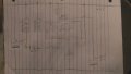
Just did a circuit for a 555 timer that I could use some advice on. What I'm looking for is when 12 volt DC is applied and constant until voltage is removed my circuit works for approx 3 to 5 seconds. Then it is repeated when power is removed and applied again. I have tried it on bread board and works like I want. But a beginner I would appreciate a second look to see if there would be any long term issues.
Also where I have light on the diagram I wondering if I should do a relay seeing I'm looking to hook up a battery powered spark Igniter from home Depot to ignite propane gas from a solenoid. Unless someone can send me in the right direction to build my own. Also wondering if there's a way to hook up a pointiometer to change duration.
I have another thread here that I'm using it for. I'm getting rid of the thermocouple and going with an igniter instead of pilot.
http://forum.allaboutcircuits.com/threads/solenoid-valve-for-beer-brewing.114914/

Any advice would greatly be appreciated. Thanks
Steve.
Also where I have light on the diagram I wondering if I should do a relay seeing I'm looking to hook up a battery powered spark Igniter from home Depot to ignite propane gas from a solenoid. Unless someone can send me in the right direction to build my own. Also wondering if there's a way to hook up a pointiometer to change duration.
I have another thread here that I'm using it for. I'm getting rid of the thermocouple and going with an igniter instead of pilot.
http://forum.allaboutcircuits.com/threads/solenoid-valve-for-beer-brewing.114914/
Any advice would greatly be appreciated. Thanks
Steve.
Attachments
-
 60 KB Views: 2


