Adjustable Constant Current LED Power Supply

Thread Starter

Tonecat

Joined Apr 7, 2011
15
Hello Everyone,

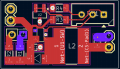
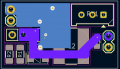
This is my first post in a long time. I am a hobbyist with a limited knowledge of electronics. I have successfully built and repaired several vacuum tube amplifiers and various guitar pedals. I recently have delved into the world of LED lighting. I am looking to build my own battery/DC powered LED driver that is efficient (since it will be using batteries as the power source), is dimmable and adjustable for constant current output. This way I can make one battery powered power supply to run many different types of LED's. I have found this design and would like to modify it for my project. I have the original schematic loaded into KiCad for the changes to be made.

https://www.artekit.eu/doc/guides/ak-led-driver/ I can post the schematic from KiCad, but don't know if it violates the forum rules???

Instead of having four fixed output currents, I would like to make the power supply adjustable for various constant current loads between 20mA and 1A, or if this is not doable, between 20mA and 350mA for lower powered projects, and 350mA to 1A for higher powered ones. It would seem to me that all I would have to do is sub the multiple resistor arrays with one fixed resistor and a small potentiometer? Or possibly with another chip/resistor combo? Also, once I have figured out the power supply, I would like to add the ability to charge the batteries. (Thinking of two 18650 (or similar) 3.7v batteries in series for the power source. If anyone could please advise me on this, I would greatly appreciate it!

Thank You!
 

crutschow

Joined Mar 14, 2008
38,423
The spec says:
  • Drive with DC voltage (between 0.3V and 2.5V) to adjust output current from 0 to 100%. Linear adjustment ranges from 5% to 100% of selected output current.
So if you add a pot to give the 0.3V to 2.5V voltage, you should be able to adjust the current from zero to the maximum 1A.

You could add a 2.5V reference, such as the TL431, to give a stable voltage to the pot, so the current doesn't vary as the battery voltage drops during discharge.
LTspice sim of example circuit below for a pot rotation of 0 to 100%:

1734373417061.png
I can post the schematic from KiCad, but don't know if it violates the forum rules?
None that I'm aware of.
 
Last edited:

ronsimpson

Joined Oct 7, 2019
4,664
Using CurtsChow's idea:
Setting the board from Post #1, set to 1A you and adjusting the control voltage from 0.4 to 2.5 you should get a constant current of 1A to 20mA.
1734377145084.png
The graph is hard to understand. There is no 80% line no 50% line no 10% line. So, I don't really know.

Current flows through the solder jumpers on the board. Do not add long wires or switches that have resistance. I would add a jumper like this picture. This way you can change the board for 300mA max so you can get to low current.
1734377587576.png
I would add a place to connect in a voltmeter because the voltage on a diode tells us about what type of LED you have.
 
Last edited:

ronsimpson

Joined Oct 7, 2019
4,664
What's hard?
In the graph the red arrows (vertically) are 10 long. The blue arrows are 10 long. Red10 and Blue10 look very different in length. The graph is not linear.
1734381169664.png
On my computer there are two different versions of the data sheets. The new version has a better graph. Now this graph I agree with. The lines are evenly spaced.
1734381511165.png
 

Thread Starter

Tonecat

Joined Apr 7, 2011
15
Thank you for the help! I would like to add the TL431 and a small precision pot to adjust the current output, however, I'm not quite sure how to implement it into this design? I would also like to eliminate the unused resistors (R3,R4) as I only would need to have the option for 300mA and below and up to 1A output current. As far as I can tell from the original schematic, R1 is .33ohm and is in circuit all the time. If I combine the values of R2 ,R3, and R4 I come up with 1.35 ohms to get up to 1A output current, so if I change the value of R2 to 1.35ohms and add a jumper, would this work? Here is the original schematic. Again, thank you for your help and ideas!
 

Attachments

crutschow

Joined Mar 14, 2008
38,423
I would like to add the TL431 and a small precision pot to adjust the current output, however, I'm not quite sure how to implement it into this design?
The Out of my circuit connects to the CTRL input of Driver circuit.
Here is my attempt at the new schematic.
Your schematic does not correctly show my circuit connections.
Also the ground (common) of my circuit connects to your GND connections.
 

Thread Starter

Tonecat

Joined Apr 7, 2011
15
The Out of my circuit connects to the CTRL input of Driver circuit.

Your schematic does not correctly show my circuit connections.
Also the ground (common) of my circuit connects to your GND connections.
Does this look better? Thanks again for your patience and help! Also, is my resistor and jumper layout ok?
Screenshot 2024-12-16 191152.png
 

crutschow

Joined Mar 14, 2008
38,423
Does this look better? Thanks again for your patience and help! Also, is my resistor and jumper layout ok?
Yes, It all would appear to be correctly connected.

Drawing component sideways, instead of vertical with the grounds towards the page bottom and the plus voltage towards the page top, makes the schematic more difficult to read.
I had to look at my part of the circuit several times to see that it was correct.
A neat schematic is not always the best schematic.
 

Thread Starter

Tonecat

Joined Apr 7, 2011
15
Hello again. Thanks again for all the comments and help. I have included an image of my board layout. Could any of you pros have a look at it to see if there might be any problems? This is my first attempt at a board build. Just want to make sure everything looks good as far as component placement. Board 1.jpgBoard 2.jpg
 

ronsimpson

Joined Oct 7, 2019
4,664
I increased the copper area on pin1 "SW" I am trying to get some heat out of the parts. And there is 1A flowing there.
Pin5 is Vin. Wade traces pull the heat out of IC and diode.
Pin 2 is ground. It should connect to as much copper as possible. Use VIAs to connect current and heat to the other side of the board. (Assuming the back side is mostly copper and ground)
I would have put the input capacitor near the IC from pin 2 to pin 5. Short wide traces. It does not need to be on the input connector.
There is current flow in the ground. Cap output, Cap input, IC-2 need to connect well.
VIAs cost you nothing. Use them to stich the top side traces to the bottom side ground fill.
The high current low ohm resistors have 1A so use large traces.
Only use thin traces where the TL431 is, resistors and Pot.

1734536908469.png
 

Thread Starter

Tonecat

Joined Apr 7, 2011
15
I increased the copper area on pin1 "SW" I am trying to get some heat out of the parts. And there is 1A flowing there.
Pin5 is Vin. Wade traces pull the heat out of IC and diode.
Pin 2 is ground. It should connect to as much copper as possible. Use VIAs to connect current and heat to the other side of the board. (Assuming the back side is mostly copper and ground)
I would have put the input capacitor near the IC from pin 2 to pin 5. Short wide traces. It does not need to be on the input connector.
There is current flow in the ground. Cap output, Cap input, IC-2 need to connect well.
VIAs cost you nothing. Use them to stich the top side traces to the bottom side ground fill.
The high current low ohm resistors have 1A so use large traces.
Only use thin traces where the TL431 is, resistors and Pot.

View attachment 338321
Wow! Thank you for the extremely useful info!! I am using KiCad, so I will have to figure out how to widen the traces. Are there such things as solid vias, instead of a hole?? I have all grounds and a couple other traces on the back of the board. I wasn't able to do it any other way. I will work on moving components and your suggestions. Thank you!
 

ronsimpson

Joined Oct 7, 2019
4,664
Thankyou.
Do an area fill on the back side to make it all ground.
I don't like long traces on J3.
C1 at IC1.
1734541947520.png
Here are the high current paths.
1734542242495.png
 

Thread Starter

Tonecat

Joined Apr 7, 2011
15
Hello Again! After much experimentation in KiCad, here is my updated layout with suggested component moves, and larger traces/planes. The net in purple is the only one on the back of the board other than the grounds. I wasn't able to get many extra vias on the board for cooling. Do you think this will be a problem? Also, the inductor shown on the original schematic isn't in stock anywhere. I tried to find one that had similar specs. the detail sheet is posted below. Is that inductor a good fit for this circuit? If you spot any other areas of concern or problems, please let me know. Thanks again for your time and knowledge!!

Screenshot 2024-12-19 083612.pngScreenshot 2024-12-19 083850.pngScreenshot 2024-12-19 085130.png
 

Attachments

sparky 1

Joined Nov 3, 2018
1,218
The RM9003B are inexpensive and work well with leds. Why not parallel ? Why not replace the resistors with dual potentiometer,
The video demonstrates how these semiconductors higher voltage characteristics lend themselves to CC for led lighting.
I am not sure what that (old) led bulb in the video is? If you think about CC (power supply) without an up converter then it is easier to filter EMI.
Buck boost can be noisy, As cheap goes it needs lots of filtering. Keeping it simple.: AC mains > rectifier > (linear filter board) > led string.
Making a constant current source is different for leds because the understanding and approach to an led constant current source
uses the specific criteria of leds. The mystery module does not have We need to stay on pace with change by using datasheet specifications.

A good variable constant current source is expensive, it is for applications with high requirements. For example medium and high current laser diodes.
Many of the lower end hobby applications use LM358 Mosfet, a decent "current sense resistor" and Vref. For more utility adding different ranges offer more precision. In the lower range the circuit uses an op amp with lower current capability.

I translated the RM9003B datasheet attached below, the translation did not translate the formulas however the video explains formulas.


Attachments

Last edited:

Thread Starter

Tonecat

Joined Apr 7, 2011
15
I sent the board files off to the fabricator. Getting 3 for now to see how things work out. I appreciate everyone's help and comments. I just wanted to build something myself and learn some things along the way! Thanks again! Happy Holidays!!
 

sparky 1

Joined Nov 3, 2018
1,218
Constant Current a simple demonstration for effective teaching.
The TL431 mentioned in post #8 because of it's relative simplicity has the advantage for teaching CC as a circuit.
The circuit is derived from a current mirror. It is posted here so it can be found hopefully the search engine will pick it up.
Constant Current can be a challenge. The number of misunderstandings about current mode reflects the teaching.
The video below fills that gap by demonstrating CC with the TL431 and BJT transistor.
The video includes key elements which includes a clear demonstration of concept, the correct math and a simulation.

 
Last edited:
Top