Additional Section on FSMs

Thread Starter

tshuck

Joined Oct 18, 2012
3,534
Hey folks,

So, in an effort to contribute to the e-book, I have created an additional section to coincide with the existing section on FSMs, namely this one. Ideally, more sections will be added, with the ultimate goal to break FSMs out to a new chapter(they deserve it:p). I may, or may not, take up that challenge...

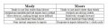
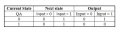
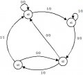
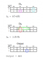
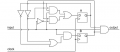
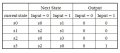
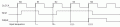
The idea of this section is to introduce the reader to the different types of FSMs after the initial section.

The following post will be the working version. Any and all modifications will be done in in it.

Please comment and verify if you have time:)

This is a review process, so if you notice an error, no matter how big, or small, please leave a comment. I'm open to suggestions...

Thanks for looking, and, here it goes!


EDIT: I can only link 6 images! No idea how I'm going to fix that one :confused:

I guess there will be subsequent posts.. perhaps a moderator would be so kind as to help rearrange the posts so they make sense again, or possibly combine them into one proper post?;)
 
Last edited:

Thread Starter

tshuck

Joined Oct 18, 2012
3,534
Another look at FSMs

There are actually two types of finite state machines: Moore and Mealy. Both types of FSMs accomplish the same thing, however they go about doing so in different ways. The type discussed in the previous section is called a Moore Machine, so named after its inventor - Edward F. Moore. Within this scheme, the outputs of the state machine are dependent upon the current state only, as we saw before. Mealy machines, on the other hand, have their outputs dependent on both the system inputs and current state. Let us consider the example in the previous section: an edge detector.

For the Moore machine, we have already defined the system as below:

Implementing this state machine with D flip-flops resulted in the following circuit:

Notice the output, Y, is comprised only of the outputs, QA' and QB, representing a current state of 01 without any dependence on the input.

The Mealy Machine
Now, let us examine this same concept from the point of a Mealy Machine. Since we have already described the function of our state machine, the first thing to do, as in the Moore machine, is to determine the state diagram. This time, however, our diagram will look a bit different. Since our output is dependent upon both input and output, the state need only maintain whether or not the button was pressed previously. Since only two states are required, we can define them as follows: 1 = button has been pressed, 0 = button has not been pressed. The output will be determined by which state is the current state and what the input is during that state, to apply this concept to our current solution, the output is 1 only when in the 'button not pressed' state and when the button is pressed.

Given this function definition, our state diagram looks like this:

Notice that there is no other quantity within our states, simply the state label, soon to be a binary number. This is because, as we've said, the output is not only dependent upon current state. There are, however, two numbers for each state transition. The top number is the system input with the bottom number representing the output of the system. Observing the diagram, there is only one place the output is 1, when the current state is 'button not pressed' and the input is 1, coinciding with our previous system definition!

Next, we create the state table:

From this description, we can see that the output must be current_state' AND input, as seen below:

You will notice that this uses only a single d flip-flop and an AND gate to accomplish what took the Moore Machine two flip-flops, one three-input AND and two two-input AND gates to accomplish. Indeed, we can say that, in general, it takes a Mealy Machine less hardware to implement the same function of a Moore Machine!

As a result, the propagation delay from the Mealy machine is much less than its functionally equivalent Moore implementation.

You may ask why anyone would use a Moore Machine, and your question is valid, however, as many things in electronics, there are trade-offs to be had:
 
Last edited:

Thread Starter

tshuck

Joined Oct 18, 2012
3,534
Let us now take a more complex example. This time, we will make a Mealy machine to determine if a 4-bit sequence is present in a stream of binary numbers. We will look for the input: 1011.

So, we shall read the inputs and output a 1 only when the input sequence is 1011. Let us create our state diagram, first start with state s0 to denote the condition that no numbers have been entered yet. If the input received is a 1, the first in our sequence, we will move to the next state, s1. However, if the first input is a 0, we know the sequencehas not been entered and we stay in the initial state.

Input Sequence: 1 - - -

Considering state, s1, there are two possible options the sequence can take, depending on what the input is. If the input is 0, we progress to the next state, s2. Now, take a moment and ponder this next question: where do we go if the input is 1? Do we return to initial state since the input sequence is 11-- and we know the desired sequence should start with 10--?

No. We know the desired sequence begins with 1, so any 1 may be the beginning of the desired input sequence! So, if our input, while in s1, is 1, we return to s1, like so:

Input Sequence: 1 0 - -

Now we are in s2, our input sequence has been 10-- so far. Again, there are only two possible states we can move to, since our input is only a single, binary signal. So, if our input is 1, we move on to state s3, but what happens if we get a 0? If we were to get a zero while in state s2, our input sequence would be: 100-. Does that sequence occur anywhere in our desired sequence? No. Therefore, we have no choice but to return to the initial state, s0.

Input Sequence: 1 0 1 -

So, here we are, state s3, the final state. If our input is 0, what happens? Well, that would mean our input sequence has been: 1010. Where do we go? Do the last few numbers in the sequence occur in our desired sequence? Why, yes, 10 is the first two entries in our desired sequence! So, we go to where our input sequence is 10--, or state s2. If, however, we get 1 while in state s3, we have received: 1011, our desired sequence! We must signal that we have received our sequence, output a 1!

That brings us to our next dilemma, where do we go from here? Well, there are two options, depending on how we want our state machine to behave:
  • The last 1 counts for the first input for the next sequence, or
  • The whole sequence must be re-entered before another sequence is recognized.
Whichever we choose, the machine is valid, we only are changing how it behaves after the input is received. This change in behavior manifests itself as which state we return to after we've received the desired sequence. We shall make the system enter the whole 4-bit sequence after the first is recognized, therefore, we shall return to state s0, so that the user has to re-enter the whole sequence before the system will recognize it again.

If we had wanted the last 1 to count for the beginning of the next code, we would have returned to state s1, instead.

There we are! We have designed a Mealy state machine! Well, not quite yet. We have, thus far, only described our state machine's behavior.
 
Last edited:

Thread Starter

tshuck

Joined Oct 18, 2012
3,534
It's now time to create our state table.

Expanding it to account for our state inputs:

Now we must determine our input and output-forming logic:

As expected in a Mealy machine, the output is determined by both inputs and outputs, this is a good point to check to make sure that this is the case. If your output doesn't include an input, your Mealy machine is wrong.

From this, we can design our circuit:

There we have it! A Mealy state machine that determines if the input sequence is 1011.

There is, however, a problem: when the input is 101 and the input remains 1, the output goes high! This is because the state machine is in state s3 and the input is 1, the correct sequence. The system would appear to determine it has received the desired sequence after only 101! The thing to remember, though, is that the system would be sampled at the positive edge of the clock, so, if the input sequence was, indeed, 1011, the output would be recognized at the point of the last pulse, where the input is 1011.

You can see that using a Mealy machine in this instance could be a poor design choice. What if the state machine fed an asynchronous ripple counter to count the number of times the desired sequence was detected? We could be in trouble when the input toggles while in state s3! However, if the state machine was fed a signal from a synchronous input and outputted to a synchronous device, all is well; the inputs would only change at the positive edges of the clock and the inputs would be sampled at the positive edges of the clock.
 
Last edited:

Thread Starter

tshuck

Joined Oct 18, 2012
3,534
The Synchronous Mealy Machine
The Synchronous Mealy Machine takes into account the potential problems with an asynchronous output of the Mealy machine and solves it by forcing the outputs through a flip flop in order to synchronize them with the system clock. The synchronous Mealy machine is sometimes referred to as a Moore machine, however, the number of flip flops used is not dependent on the number of states, but rather the number of states(Moore) - 1 + the number of outputs.

Given that basic definition, let us make our previous example into a synchronous Mealy machine:

This circuit's timing diagram is:

The output flip flop makes the output of the Mealy machine synchronous to the system clock. As a result, this implementation reduces possible glitches from an unstable input to a Mealy machine. The inclusion of this flip flop does, however, delay the output by one clock cycle.
 
Last edited:

Wendy

Joined Mar 24, 2008
23,421
Let people have a chance to give feedback, then we'll work on compiling the stuff. I'll work with you one it. You will need a pure .txt file.
 

Thread Starter

tshuck

Joined Oct 18, 2012
3,534
Let people have a chance to give feedback, then we'll work on compiling the stuff. I'll work with you one it. You will need a pure .txt file.
It's done. This is all copied out of the html file that sml2html.sed generates.

I was asking about help making the posts more cohesive instead of interrupting the post with image holding posts...or allowing more than 6 images per post on this thread...
 

takao21203

Joined Apr 28, 2012
3,702
Put it on a domain website and link it.

There are some modern image hosting services, which include thumbnail generation, and HTML code generation.

Photobucket is US based, but rather complicated to use.

Photozou is very easy to use, the shortest turnaround time for embedding images on websites. Japanese service provider. And 100% free.

Both don't have adult content so are safe.

It is really totally different if you have to upload manually via FTP, or if you can bulk upload images, bulk write the descriptions, and then can get HTML codes very easily.

I don't use photobucket anymore because it is actually far more complicated to do all these steps, the interface is rather slow.

But maybe you'd rather want to use photobucket than photozou. They don't have any english menu's or buttons.

Having such a image hosting, creating a plain webpage is a matter of minutes.
 

thatoneguy

Joined Feb 19, 2009
6,359
Question on Post #5, the lock.

Why is S3 jumping back to S2 when an incorrect bit is seen, shouldn't it jump to the beginning? Otherwise, once the 10 is known, only 11 needs to be entered for the "lock" to open, rather than the full 4 digits, in order.

To be more pedantic, add a counter so the "enter code" light (or bad code light) @ s0 flags a bad code after any 4 digits that aren't correct?
 

Thread Starter

tshuck

Joined Oct 18, 2012
3,534
Why is S3 jumping back to S2 when an incorrect bit is seen, shouldn't it jump to the beginning? Otherwise, once the 10 is known, only 11 needs to be entered for the "lock" to open, rather than the full 4 digits, in order.
as you said, the input only has to match enter 11 to have the sequence recognized, but that is the point, to recognize where in the sequence of 1s and 0s the input is, or if it is. If it went back to the beginning, the user would have to know what state the machine is in, so as to enter the correct sequence from that point. Otherwise, the user could input 101011 and not be accepted. So, If the input was 0000000001010101011010100, the FSM should indicate it received the sequence. Otherwise, the correct sequence would have to be put in only when in s0....

Perhaps calling it a passcode is a bit misleading.... perhaps I'll change that....
 

Georacer

Joined Nov 25, 2009
5,182
Yes, it is kind of misleading, if you have a preset conception of what a passcode is. Either be very specific about what you want your machine to do beforehand, or call it a language acceptor/recognizer.

Usually a keypad will buzz in distress if you input a wrong set of exactly four numbers.
 
Top