Adding voltage sources in LTSpice

Thread Starter

djsfantasi

Joined Apr 11, 2010
9,156
I think this is a simple question to which I believe I know the answer. But, I’m a little confused.

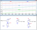
I have two voltage sources. Vo is a 1.0V source.

It is placed in series with Va, + to - Va is a linear voltage source, that over 1 second, rises from -1.0V to +1.0V

What is the output look like?

I can see the results in simulation, but in another discussion, I’m getting a different answer...

One additional modification. If I place a capacitor (for purposes of this discussion, say a 0.1uf), does the output from the three components change dramatically?

Like I said, I thought I knew the answer, but others are suggesting that my answer is wrong. I’m purposefully not including what I think, to avoid “poisoning the well”.
 

crutschow

Joined Mar 14, 2008
34,286
If the two sources are in series then the voltage across the two is simply the sum of the two voltages, polarity included.

Since these are ideal voltage sources the addition of any load, no matter what type, (except for a short, of course) will not affect that voltage at all.
 

ericgibbs

Joined Jan 29, 2010
18,767
hi dj,
Unexpected results.
Using the regular Voltage source, it looks wrong, using a Behavioural Voltage source looks OK.

Included a Test check plot for the B source.
E

Update:
A fellow member picked up a typo I had made on the ramping Voltage source definition, so the Vx plot shown in this post is incorrect.
 

Attachments

Last edited:

Alec_t

Joined Sep 17, 2013
14,280
Eric, if you use a pulse, rather than PWL, as the standard voltage source you get the right result. Also, starting your PWL at -1 sec probably has undesired consequences :).
 

ericgibbs

Joined Jan 29, 2010
18,767
hi alec.
In the past I have used the Voltage sources in series, with a start value below 0V.
Typically with IA amp signals, ie: Vbrg/2 + a 'ramp' source of say -20mV thru +20mV

That was using LTS XVI [ just installed Win 10 and LTS XVII]

I would expect an algebraic sum of the two sources to be the combined output of two voltage sources in series.
[ we get that using two behavioural voltage sources]

Interested to hear what LTS or Wiki have to say.

Eric
 

Thread Starter

djsfantasi

Joined Apr 11, 2010
9,156
I totally expected the output to be in the range of 0V to 2V. Thanks for those of you who have confirmed this.

The Va input is a voltage source determined by a .wav file. It’s range is from -1V to 1V.

In actuality, the signal, Vy, is from 0V to 2V, if it’s referenced to circuit ground instead of the virtual signal ground from a VS1053 used in an Arduino shield.

There has been some confusion suggesting that the output would go negative. I stubbornly refused to believe it.
 

BobTPH

Joined Jun 5, 2013
8,816
There has been some confusion suggesting that the output would go negative. I stubbornly refused to believe it.
What is the virtual ground voltage with respect to ground? If it is +1, say, yes, the signal would go negative relative to the virtual ground.

Bob
 

ebeowulf17

Joined Aug 12, 2014
3,307
Really?

You need a diagram to show two components in series? When I get to my LTSpice installation, I’ll upload a schematic.
I'm with @Bordodynov. The following phrase is hard to read and confusing. Missing punctuation? Not sure, but it left polarity questions lingering for me:
It is placed in series with Va, + to - Va is a linear voltage source, that over 1 second, rises from -1.0V to +1.0V
 

Thread Starter

djsfantasi

Joined Apr 11, 2010
9,156
What is the virtual ground voltage with respect to ground? If it is +1, say, yes, the signal would go negative relative to the virtual ground.

Bob
As it so happens, the virtual ground voltage with respect to ground is +1. But I’m not using virtual ground at all. I’m taking the signal with respect to circuit ground.
 
Top